Blog
Jewellok is a professional pressure regulator and valve manufacturer and supplier.

What Is the Difference Between a Safety Valve and a Pressure Relief Valve, and How Do I Select the Pressure?
- Pressure Regulator Valve Manufacturer
- 1 1 2 gas pressure regulator, 1 2 gas regulator, 1 2 propane regulator, 1/2 gas pressure regulator, 12v electric valve, 2 electric valve, adjustable propane pressure regulator, electric water valve, gas cylinder, gas pressure regulator how it works, gas regulator, gas used in semiconductor chip manufacturing, high pressure argon regulator, high pressure flexible hose pipe, high purity regulator, how a regulator works, how does a gas pressure regulator work, how gas pressure regulator works, how pressure regulator works, lab fittings exporter, pressure regulator, pressure relief valve, pressure relief valve factory, pressure relief valve manufacturer, pressure safety valve vs relief valve, propane pressure regulator valve, relief valve and safety valve difference, safety valve, safety valve and pressure relief valve, safety valve and pressure relief valve supplier, safety valve manufacturer, safety valve supplier, valve manifold box, water valve timer, what is a flame arrestor
- No Comments
What Is the Difference Between a Safety Valve and a Pressure Relief Valve, and How Do I Select the Pressure?
In industrial systems handling pressurized fluids—such as oil and gas pipelines, chemical reactors, hydrogen storage systems, steam boilers, and pharmaceutical processing equipment—maintaining safe pressure levels is critical to prevent catastrophic failures like explosions, equipment damage, or environmental harm. Safety valves and pressure relief valves (PRVs) are essential safety devices designed to release excess pressure, protecting systems, personnel, and the environment. While these terms are sometimes used interchangeably, they have distinct designs, functionalities, and applications, making it crucial to understand their differences for proper selection and use. Additionally, selecting the correct set pressure for these valves is vital to ensure effective operation and compliance with safety standards. An incorrect choice can lead to premature valve activation, system inefficiencies, or failure to protect against over-pressure. This article compares safety valves and PRVs, detailing their differences in design, operation, and applications, and provides a step-by-step guide to selecting the appropriate set pressure for industrial applications.

Defining Safety Valves and Pressure Relief Valves
Safety Valves
A safety valve is a specialized valve designed to rapidly release pressure from a system when it exceeds a predetermined set pressure, preventing catastrophic failure. Safety valves are typically used in systems handling gases or vapors, such as steam, air, or hydrogen, and are characterized by their quick, full-lift opening to vent large volumes of fluid. Once the pressure drops to a safe level, the valve reseats, stopping the release. Safety valves are commonly associated with boilers, pressure vessels, and gas systems, where rapid pressure relief is critical to prevent explosions or ruptures.
Key Features:
- Rapid, full-lift opening for high-capacity relief.
- Primarily used for gases or vapors (e.g., steam, hydrogen).
- Designed for emergency scenarios with infrequent activation.
- Often spring-loaded or pilot-operated for precise operation.
Pressure Relief Valves (PRVs)
A pressure relief valve (PRV) is a broader category of safety device that opens to release excess pressure and closes when pressure returns to a safe level. PRVs are versatile, used for liquids, gases, or mixed-phase fluids, and are designed to provide controlled, proportional relief to maintain system stability. Unlike safety valves, PRVs may open gradually, depending on the pressure increase, and are used in a wide range of applications, including pipelines, reactors, and storage tanks. In some contexts, PRVs are referred to as pressure safety valves (PSVs), particularly in oil and gas.
Key Features:
- Proportional or modulated opening for controlled relief.
- Suitable for liquids, gases, or mixed-phase fluids.
- Versatile for frequent or dynamic pressure fluctuations.
- Available in spring-loaded, pilot-operated, or bellows-sealed designs.
Terminology Note: In industries like oil and gas, “safety valve” and “PSV” are sometimes used synonymously, but safety valves are technically a subset of PRVs optimized for gas/vapor applications. This article uses distinct definitions to clarify their differences.
Detailed Comparison: Safety Valves vs. Pressure Relief Valves
To select the right valve and set pressure, it’s essential to understand the differences between safety valves and PRVs across key parameters: design, operation, applications, and performance.
- Design and Operation
Safety Valves:
- Mechanism: Feature a disc or poppet that lifts fully when system pressure exceeds the set point, rapidly venting gas or vapor. The valve reseats after a significant pressure drop (blowdown, typically 3–10% of set pressure).
- Components: Include a nozzle, disc, spring, blowdown ring, and body, often made of stainless steel (e.g., 316L) or high-nickel alloys for corrosion resistance.
- Operation: Full-lift, rapid opening maximizes flow capacity, critical for emergency relief in gas systems. Spring-loaded designs are common, with pilot-operated versions for high-pressure or precise control.
- Flow Path: Large orifice for high-capacity gas relief.
PRVs:
- Mechanism: Open gradually or proportionally as pressure increases, modulating flow to maintain system stability. Reseat closer to the set pressure (blowdown 2–5%).
- Components: Include a disc, seat, spring or pilot, and body, with materials like stainless steel, Hastelloy, or PTFE for compatibility with liquids or corrosive fluids.
- Operation: Proportional opening adjusts flow based on pressure, minimizing fluid loss. Pilot-operated or bellows-sealed designs handle variable backpressure or corrosive fluids.
- Flow Path: Smaller, controlled orifice for liquids or mixed-phase fluids.
- Key Difference: Safety valves prioritize rapid, full-lift relief for gases/vapors in emergency scenarios, while PRVs offer proportional relief for a broader range of fluids, balancing safety and system efficiency.
- Functionality and Performance
Safety Valves:
- Primary Function: Prevent catastrophic over-pressure in gas/vapor systems by quickly venting large volumes.
- Response Time: Immediate, full-lift action to address sudden pressure spikes (e.g., boiler steam surges).
- Fluid Loss: High, as the focus is on safety over fluid conservation.
- Reseat Behavior: Reseats after significant blowdown, designed for infrequent activation.
PRVs:
- Primary Function: Maintain system pressure within safe limits for liquids, gases, or mixed fluids, often with controlled release.
- Response Time: Gradual or proportional opening to match pressure increase, reducing unnecessary fluid loss.
- Fluid Loss: Minimized through modulated relief, preserving process fluid where possible.
- Reseat Behavior: Reseats closer to set pressure, allowing frequent operation in dynamic systems.
- Key Difference: Safety valves are optimized for emergency, high-capacity gas relief, while PRVs provide controlled, versatile relief for diverse fluids and scenarios.
- Applications
Safety Valves:
- Power Generation: Protecting steam boilers, turbines, and superheaters (e.g., ASME Section I applications).
- Hydrogen Energy: Safeguarding high-pressure hydrogen systems in fuel cells or refueling stations (e.g., NFPA 56 compliance).
- Oil and Gas: Venting gas in upstream wellheads or compressors.
- Chemical Processing: Releasing vapor in reactors handling volatile gases (e.g., ethylene).
- Aerospace: Managing propellant gases in rocket systems.
PRVs:
- Oil and Gas: Protecting pipelines, storage tanks, and refineries from liquid or gas over-pressure (e.g., API 520/526 applications).
- Chemical Processing: Controlling pressure in reactors with liquid chemicals or mixed-phase fluids (e.g., ammonia).
- Pharmaceuticals: Ensuring safe pressure in sterile liquid systems.
- Water Treatment: Managing pressure in water or wastewater pipelines.
HVAC: Releasing refrigerant gases or liquids in chillers.
- Key Difference: Safety valves are specialized for gas/vapor systems in high-risk, rapid-relief scenarios, while PRVs are versatile for liquid, gas, or mixed-phase systems across diverse industries.
- Regulatory Standards
Safety Valves:
- ASME Section I: Governs safety valves for power boilers, requiring annual testing and specific blowdown settings.
- ASME Section VIII: Applies to safety valves for pressure vessels, mandating testing every 1–5 years.
- NFPA 56: Specifies requirements for hydrogen systems, emphasizing rapid relief.
- ISO 4126-1: Defines global standards for gas/vapor safety valves.
- EN 13445: European standard for pressure equipment.
PRVs:
- API 520/526: Guides PRV sizing, selection, and testing in oil and gas, recommending testing every 1–5 years.
- ASME Section VIII: Covers PRVs for pressure vessels, with similar testing requirements.
- OSHA 1910.119: Mandates process safety management for hazardous chemical processes.
- ISO 4126-4: Addresses pilot-operated PRVs for liquids and gases.
EPA Regulations: Govern emissions from PRV releases (e.g., Clean Air Act).
- Key Difference: Safety valves are tightly regulated for gas/vapor applications (e.g., boilers, hydrogen), while PRVs face broader standards covering diverse fluids and industries.
How to Select the Right Valve
Choosing between a safety valve and a PRV depends on the application’s fluid type, operational needs, and safety requirements:
Choose a Safety Valve:
- For gas or vapor systems (e.g., steam, hydrogen).
- When rapid, high-capacity relief is needed (e.g., boiler protection).
- For infrequent, emergency relief scenarios.
- When compliance with standards like ASME Section I or NFPA 56 is required.
Choose a PRV:
- For liquids, gases, or mixed-phase fluids (e.g., oil, water, ammonia).
- When controlled, proportional relief is needed (e.g., pipeline pressure management).
- For frequent or dynamic pressure fluctuations.
- When compliance with standards like API 520 or ASME Section VIII is required.
Action: Assess the fluid type, relief requirements, and regulatory standards to select the appropriate valve type.
How to Select the Set Pressure
The set pressure is the pressure at which the valve begins to open, critical for ensuring safety without compromising system efficiency. Selecting the correct set pressure involves understanding the system’s operating conditions, safety requirements, and regulatory guidelines. Follow these steps:
Step 1: Determine the Maximum Allowable Working Pressure (MAWP)
- Definition: The MAWP is the maximum pressure a system (e.g., vessel, pipeline) can safely withstand, as specified by the manufacturer or design standards (e.g., ASME, API).
- Sources: Obtain the MAWP from equipment nameplates, design documents, or engineering calculations.
- Considerations: Account for system components with the lowest MAWP to ensure comprehensive protection.
- Action: Identify the MAWP of the system or its weakest component (e.g., 100 bar for a pressure vessel).
Step 2: Establish the Normal Operating Pressure
- Definition: The pressure at which the system typically operates under normal conditions.
- Importance: The set pressure must be sufficiently above the normal operating pressure to prevent premature valve activation, which can cause fluid loss or process disruptions.
- Guideline: The set pressure is typically 10–20% above the normal operating pressure, depending on standards and fluid type.
- Example: If the normal operating pressure is 80 bar, the set pressure should be 88–96 bar to avoid unnecessary relief.
Action: Document the normal operating pressure and ensure a buffer (e.g., 10–20%) for the set pressure.
Step 3: Align with Regulatory Standards
- ASME Section VIII: For pressure vessels, the set pressure must not exceed the MAWP. Multiple valves may have staggered set pressures (e.g., 100% and 105% of MAWP) for redundancy.
- API 520: Recommends set pressure at or below MAWP for PRVs, with blowdown set to ensure reseating without excessive fluid loss.
- ASME Section I: For boilers, the set pressure is typically at or slightly above MAWP, with a maximum of 3% overpressure allowance.
- NFPA 56: For hydrogen systems, set pressure ensures rapid relief to prevent flammable gas accumulation.
- Action: Consult applicable standards (e.g., ASME, API) to set the pressure within regulatory limits.
Step 4: Account for Overpressure and Blowdown
- Overpressure: The pressure increase above the set pressure during relief, typically 3–10% for safety valves and 10–21% for PRVs, depending on the standard.
- Blowdown: The pressure drop required for the valve to reseat, typically 2–10% of set pressure. Safety valves have higher blowdown (e.g., 7–10%) than PRVs (e.g., 2–5%).
- Considerations: Ensure overpressure does not exceed equipment limits, and adjust blowdown to minimize fluid loss or system cycling.
- Example: For a 100 bar MAWP system, a safety valve with a set pressure of 100 bar may allow 3–10 bar overpressure (103–110 bar) and reseat at 90–93 bar (7–10% blowdown).
Action: Specify overpressure and blowdown settings based on system tolerances and manufacturer recommendations.
Step 5: Consider System Dynamics
- Pressure Spikes: Systems with frequent pressure surges (e.g., pump startups) may require a higher set pressure to avoid chatter (rapid opening/closing).
- Backpressure: Account for downstream pressure (e.g., in discharge lines), which can affect valve performance. Bellows-sealed PRVs or pilot-operated valves handle variable backpressure.
- Fluid Dynamics: Gases require faster relief (safety valves), while liquids need controlled release (PRVs) to prevent water hammer or cavitation.
- Action: Analyze system dynamics (e.g., surges, backpressure) and select valve designs to mitigate operational issues.
Step 6: Verify with Sizing Calculations
- Valve Sizing: Ensure the valve’s orifice size and flow capacity meet the required relief rate, calculated using standards like API 520 or ASME Section VIII. Undersized valves fail to relieve sufficient pressure, while oversized valves cause instability.
- Tools: Use manufacturer sizing software or engineering calculations to determine the required flow area based on fluid type, pressure, and temperature.
- Example: For a steam boiler with a 100 bar MAWP, calculate the required orifice size to relieve 500 kg/h of steam at 110 bar overpressure.
Action: Perform sizing calculations or consult supplier tools to confirm the valve’s capacity matches relief needs.
Step 7: Test and Validate Set Pressure
- Bench Testing: Test the valve on a certified bench to verify set pressure, blowdown, and reseat performance (e.g., per ASME PTC 25 or API 527).
- In-Situ Testing: Use portable devices to confirm performance under actual conditions, minimizing downtime.
- Calibration: Adjust set pressure during installation or maintenance to account for system-specific factors (e.g., backpressure).
- Action: Schedule initial and periodic testing to validate set pressure and ensure compliance.
Challenges and Solutions
- Challenge: Premature valve opening due to low set pressure.
- Solution: Set the pressure 10–20% above normal operating pressure and test for stability.
- Challenge: Valve chatter or instability.
- Solution: Adjust blowdown settings and use pilot-operated or bellows-sealed valves for dynamic systems.
Challenge: Regulatory complexity.
- Solution: Engage compliance experts and adhere to standards like ASME or API.
Challenge: Incorrect sizing or capacity.
- Solution: Use sizing calculations and consult manufacturer data to match valve capacity to relief requirements.
Emerging Trends
- Smart Valves: IoT-enabled valves with sensors monitor pressure and performance, enabling predictive maintenance.
- Sustainable Materials: Eco-friendly alloys and coatings reduce environmental impact.
- Digital Twins: Virtual models optimize valve selection and set pressure settings.
- Automated Testing: Portable rigs improve testing accuracy and reduce downtime.
- Impact: These trends enhance reliability, compliance, and efficiency in valve selection and operation.

Conclusion
Safety valves and pressure relief valves are both critical for protecting pressurized systems, but they serve distinct roles. Safety valves are specialized for rapid, full-lift relief of gases and vapors in high-risk applications like boilers and hydrogen systems, while PRVs offer versatile, proportional relief for liquids, gases, or mixed fluids across diverse industries. Their differences in design, functionality, and applications necessitate careful selection based on fluid type, relief needs, and regulatory standards. Selecting the correct set pressure involves determining the MAWP, establishing a buffer above normal operating pressure, aligning with standards, and accounting for overpressure, blowdown, and system dynamics. By following the outlined steps—defining system requirements, performing sizing calculations, and validating through testing—organizations can ensure safe and efficient valve operation. Emerging trends like smart valves and digital twins further enhance performance, supporting safety and innovation. By understanding the differences between safety valves and PRVs and applying a systematic approach to set pressure selection, stakeholders can protect critical systems, ensure compliance, and drive operational success.
For more about what is the difference between a safety valve and a pressure relief valve, and how do i select the pressure?, you can pay a visit to Jewellok at https://www.jewellok.com/ for more info.
Recent Posts
How to Safely Operate a TMA Gas Changeover Manifold
How to Choose an Ultra High Purity CO2 Pressure Reducing Valve
The Top High-Pressure Argon Gas Regulator Manufacturer in China
How to Choose a Gas Cylinder Manifold System
Tags
Recommended Products
-
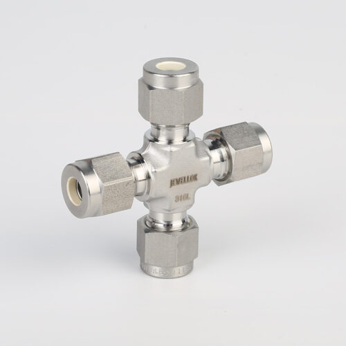
7102L Stainless Steel 316L SS Union Cross Ultra High Purity Long Arm Union Elbow Tee Cross Butt Weld Fittings
-
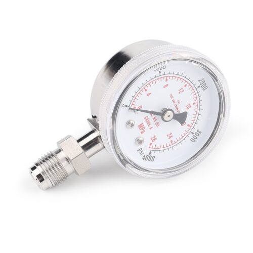
Ultra High Purity Oxygen Pressure Gauge For Semiconductor Gases JG Series Pressure Instruments For Semiconductor Manufacturing
-
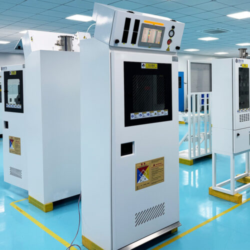
Ultra High Purity Trimethylaluminum TMA Gas Cabinet Liquid Delivering Cabinet Used For Specialty Gas Delivery System In Semiconductor
-

Fully Automated Gas Cabinet For Precise UHP Gas Delivery And High Purity Gas Delivery Systems JW-300-GC
-
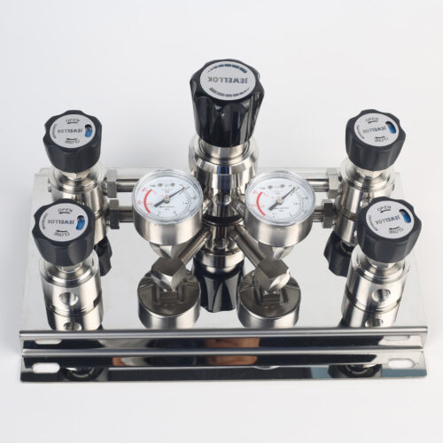
Single Stage Wall And Cabinet Mounting Pressure Control Panels JSP-2E Series For High Purity Gases
-
768LN Stainless Steel Male Pipe Tube Butt Weld Connector And Tube Fittings Supplier
-
Semi-Automatic VMB Gas Cabinet With Semiconductor Valve Manifold Box Diaphragm Valves And Gas Pressure Regulators
-
Stainless Steel High Pressure Specialty Gas Changeover Manifold For High Purity Oxygen Nitrogen Argon Helium Hydrogen Co2