Valves Manufacturer Tel: +86 13380377051
")
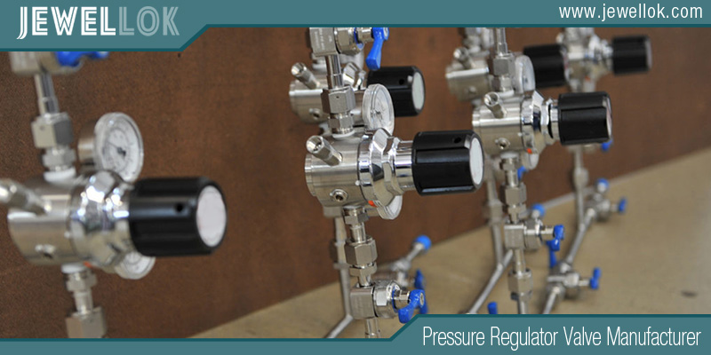
How Does the Internal Pressure Relief Mechanism of a High-Pressure Argon Gas Regulator Work to Prevent Overpressure Hazards?
High-pressure argon gas regulators are essential devices in industries ranging from welding and metal fabrication to semiconductor manufacturing and analytical laboratories. Argon, an inert noble gas, is stored in cylinders at pressures often exceeding 3,000 pounds per square inch gauge (psig), and regulators reduce this to usable levels while maintaining stability and safety. Overpressure hazards—such as cylinder rupture, equipment damage, or even explosions—pose significant risks if not properly managed. The internal pressure relief mechanism plays a pivotal role in mitigating these dangers by automatically venting excess pressure, ensuring the system remains within safe limits.
This article delves into the workings of the internal pressure relief mechanism in high-pressure argon gas regulators, explaining its operation and hazard prevention capabilities. It also explores critical design considerations that enhance reliability during long-term operation under demanding conditions. Drawing from technical principles and industry standards, we highlight how these features safeguard processes involving argon, where precision and purity are paramount. Understanding these aspects is crucial for engineers, technicians, and safety professionals to select and maintain regulators that minimize downtime and risks.
High-pressure regulators for argon typically handle inlet pressures up to 6,000-10,000 psig, with outlets ranging from 0-500 psig or higher in specialized models. They incorporate components like diaphragms, poppet valves, and springs to control flow, but the relief mechanism adds a layer of protection against failures such as seat leaks or thermal expansion. In the context of argon, an asphyxiant at high concentrations, reliable relief prevents not only pressure-related incidents but also potential gas releases in confined spaces.
Understanding High-Pressure Argon Gas Regulators
Before examining the relief mechanism, it’s essential to grasp the regulator’s core functionality. A pressure regulator reduces high inlet pressure (P1) to a stable outlet pressure (P2) using three key elements: the loading mechanism (e.g., a spring or dome), the sensing element (e.g., a diaphragm or piston), and the control element (e.g., a poppet valve).
In a typical single-stage regulator, gas enters the high-pressure chamber, and the loading spring compresses the diaphragm, opening the valve to allow flow into the low-pressure chamber. The diaphragm senses P2 and balances against the spring force to maintain equilibrium.
For high-pressure argon applications, regulators often use stainless steel or brass bodies with CGA 580 connections, ensuring compatibility and purity.Dual-stage designs, common for precision needs, reduce pressure in two steps: the first stage to an intermediate level, and the second to the final output. This minimizes effects like decaying inlet characteristic, where P2 rises as cylinder pressure drops.
Overpressure can occur from regulator failure (e.g., stuck valve), inlet surges, or no-flow conditions causing thermal buildup. Without relief, pressures could exceed the regulator’s proof pressure (150% of rated) or burst pressure (400% of rated), leading to catastrophic failure. The internal relief mechanism addresses this by integrating venting capabilities directly into the regulator.
How the Internal Pressure Relief Mechanism Works
The internal pressure relief mechanism in high-pressure argon gas regulators is designed to automatically detect and alleviate excess downstream pressure, preventing hazards without requiring external devices. Unlike standalone pressure relief valves (PRVs), which vent to atmosphere upon exceeding a setpoint, internal mechanisms are built into the regulator for compact, integrated protection.
- Core Operation
In many regulators, the relief mechanism operates via self-venting or captured-venting designs. In a self-venting setup, when downstream pressure (P2) exceeds the setpoint—due to creep (slow pressure rise from seat leakage) or lockup (pressure increase at zero flow)—the diaphragm flexes upward, opening a secondary valve or port in the bonnet. This vents excess gas through the regulator’s vent hole, reducing P2 until equilibrium is restored. For argon, this venting is safe as it’s inert, but in dead-ended systems (no downstream flow), it prevents buildup that could damage gauges or lines.
Captured-venting enhances safety by directing vented gas through a separate port to a safe location, ideal for indoor or hazardous environments. It features a positionable bonnet (rotatable 360 degrees) and often a tied diaphragm, where the valve stem is mechanically linked to the diaphragm. If P2 rises, the diaphragm pulls the stem tighter against the seat, compressing contaminants and achieving positive shutoff while venting excess. This minimizes leaks and protects the diaphragm from rupture.
Internal relief valves (IRVs) are another common type, integrated into the regulator body. They open when P2 exceeds the regulator’s setpoint plus lockup pressure, allowing gas to escape through the vent. The discharge starts based on the relief spring’s range, with capacity depending on inlet pressure, orifice size, and vent dimensions. For example, in a regulator set at 50 psig, the IRV might activate at 60 psig, venting until pressure drops.
In dual-stage regulators, relief can occur between stages. If the first-stage valve leaks, intermediate pressure rises, and safety valves vent to prevent overload and potential explosion. This is crucial for high-pressure argon, where cylinders can reach 6,000 psig.
- Force Balance and Activation
The mechanism relies on force balance: downstream pressure acts on the diaphragm’s underside, opposing the spring load. When P2 exceeds the setpoint, the force overcomes the spring, deflecting the diaphragm to open the relief path. The valve “cracks” open proportionally, with crack-to-reseat pressures within ±2% of setpoint for precision. Unlike pop-type PRVs that open fully, internal mechanisms throttle for controlled relief, avoiding instability.
For argon regulators, helium leak testing ensures low leakage rates (e.g., <1×10^-9 atm cc/sec He), preventing unintended venting. The process is automatic and self-resetting, requiring no manual intervention unless underlying issues like contamination persist.
Prevention of Overpressure Hazards
The internal pressure relief mechanism directly counters overpressure hazards by maintaining system integrity and protecting personnel and equipment. Overpressure in argon systems can stem from regulator malfunctions, such as a failed poppet valve allowing full inlet pressure downstream, or external factors like temperature rises causing gas expansion in closed systems.
- Hazard Mitigation Scenarios
In a wide-open failure, where the control element sticks open, the relief mechanism vents gas equivalent to the regulator’s maximum flow at high inlet pressure, limiting buildup to safe levels (e.g., <10 psig above setpoint). For argon cylinders at 3,000 psig, this prevents downstream lines from exceeding their MAOP, avoiding bursts.
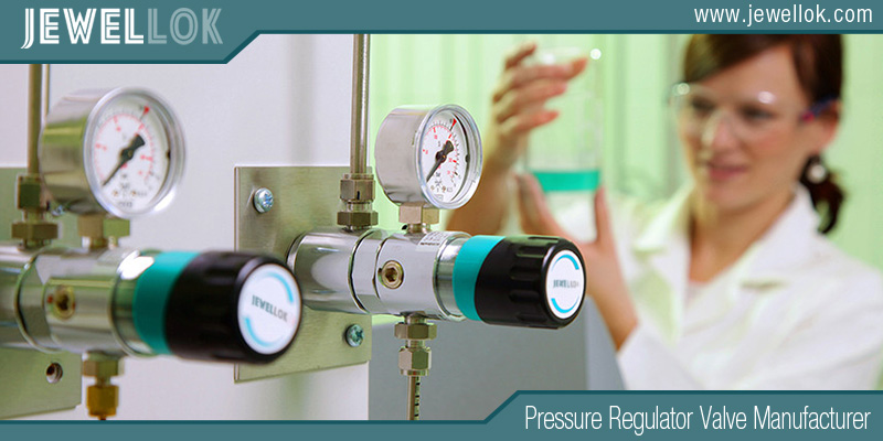
Thermal expansion in no-flow conditions (e.g., locked valves) can raise pressure by 0.8 in. w.c. per °F, but relief activates to vent incrementally, preventing creep to dangerous levels. In laboratories using argon for chromatography, this ensures consistent pressure without risking instrument damage.
The mechanism also addresses decaying inlet effects: as cylinder pressure drops, single-stage regulators may increase P2, but relief vents any excess, maintaining safety. In dual-stage setups, inter-stage relief prevents first-stage failures from overloading the second stage.
Advantages include high reliability (less prone to blockage), self-alarming via venting (indicating issues), and cost-effectiveness compared to external PRVs. However, for populated areas, captured-venting reduces noise and gas release hazards. Overall, it keeps systems operational during faults, unlike slam-shut devices that isolate supply.
In argon-specific contexts, like welding, relief prevents arc instability from pressure spikes, while in semiconductors, it safeguards purity by minimizing uncontrolled releases.
Design Considerations for Reliability Under Long-Term High-Pressure Operation
Ensuring the relief mechanism’s reliability in long-term operation requires careful design, focusing on materials, stability, and maintenance. High-pressure argon gas regulator must withstand cycles of pressure fluctuations, potential contaminants, and environmental stresses over years.
- Materials and Construction
Material selection is critical: stainless steel diaphragms and bodies (e.g., 316L) resist corrosion and offgassing, essential for argon’s high purity needs (≥99.995%). Metal-to-metal seals provide leak-free performance, outperforming elastomers that degrade. Barstock construction reduces internal volume, minimizing dead space and adsorption of moisture during cylinder changes. For high pressures (up to 10,000 psig), piston-sensed designs with O-rings and back-up rings handle forces, while tied diaphragms enhance sealing by compressing debris. Coatings like Siltride or Silcolloy improve corrosion resistance, extending life in harsh environments. Helium leak testing certifies integrity, with rates below 1×10^-9 atm cc/sec ensuring no long-term leaks.
- Staging and Performance Metrics
Dual-stage regulators offer superior reliability by reducing decaying inlet effects (e.g., 0.1 psig rise per 100 psig drop) compared to single-stage (7 psig/100 psig). This stability prevents frequent relief activation, prolonging component life. Balanced main valves minimize seat load at high pressures, allowing larger orifices without excessive wear. Key metrics include droop (outlet drop with flow, minimized by low-droop bonnets), lockup (rise at zero flow, <2% of setpoint), and repeatability (consistent return to setpoint). Venturi boost compensates for droop at high flows, enhancing long-term performance.
- Stability and Vibration Resistance
Designs must avoid resonance: harmonic (non-destructive hissing from diaphragm vibration at high P1/low P2) or hydraulic (destructive chattering from poor lubrication). Damping balances response speed and stability, preventing hunting oscillations. Pilot-operated regulators provide accuracy but slower response; spring-loaded offer speed for dynamic loads.
- Maintenance and Environmental Factors
A maintenance plan is vital: daily leak checks, monthly inspections, quarterly cleaning, annual seal replacements using OEM parts. Sizing considers max flow, inlet/outlet pressures, temperature (-40°F to 165°F), and media compatibility. For long-term use, filters prevent blockage, and straight pipe runs (≥6 diameters) ensure stability.
Heated models prevent Joule-Thomson cooling in high-flow argon, avoiding condensation In high-vibration settings like aerospace, robust materials and balanced valves maintain reliability.
Conclusion
The internal pressure relief mechanism in high-pressure argon gas regulators—through venting, tied diaphragms, and IRVs—effectively prevents overpressure hazards by automatically relieving excess pressure, safeguarding against ruptures and releases. Design considerations like stainless steel construction, dual-staging, and rigorous testing ensure reliability over long-term operation, minimizing wear and instability. As industries demand higher precision, advancements in materials and smart monitoring will further enhance these systems. Proper selection and maintenance are key to leveraging these features, ensuring safe and efficient argon handling.
For more about how does the internal pressure relief mechanism of a high-pressure argon gas regulator work to prevent overpressure hazards, you can pay a visit to Jewellok at https://www.jewellok.com/ for more info.
-
 and chemical delivery system (cds (2)")
Automated Bulk Liquid Chemical Delivery System (BCDS) with PLC Controls for High-Volume Industrial Fluid Transport
-
 and chemical delivery system (cds (4)")
UHP Bulk Liquid Chemical Delivery System (BCDS) Implementation for High-Efficiency Photovoltaic and Solar Cell Production Lines
-

771LF Female Run Tee | Stainless Steel Tube Fitting Compression Fittings 1/4 In 3-Way Tee Female Run Tee
-

Ultra High Purity Pressure Gauge For Laboratory And Semiconductor JR Series
-

739 High Purity LMR Male Adapter Tube To Pipe Fittings And Adapters
-

Ultra High Purity Trimethylaluminum TMA Gas Cabinet Liquid Delivering Cabinet Used For Specialty Gas Delivery System In Semiconductor
-

316L Stainless Steel Tube Butt Weld Reducing Fittings Union Reducer RW Series Ultrahigh Purity Process
-

High Purity High Pressure Stainless Steel Needle Valve Natural Gas Flow Control Valve JNV Series