Blog
Jewellok is a professional pressure regulator and valve manufacturer and supplier.
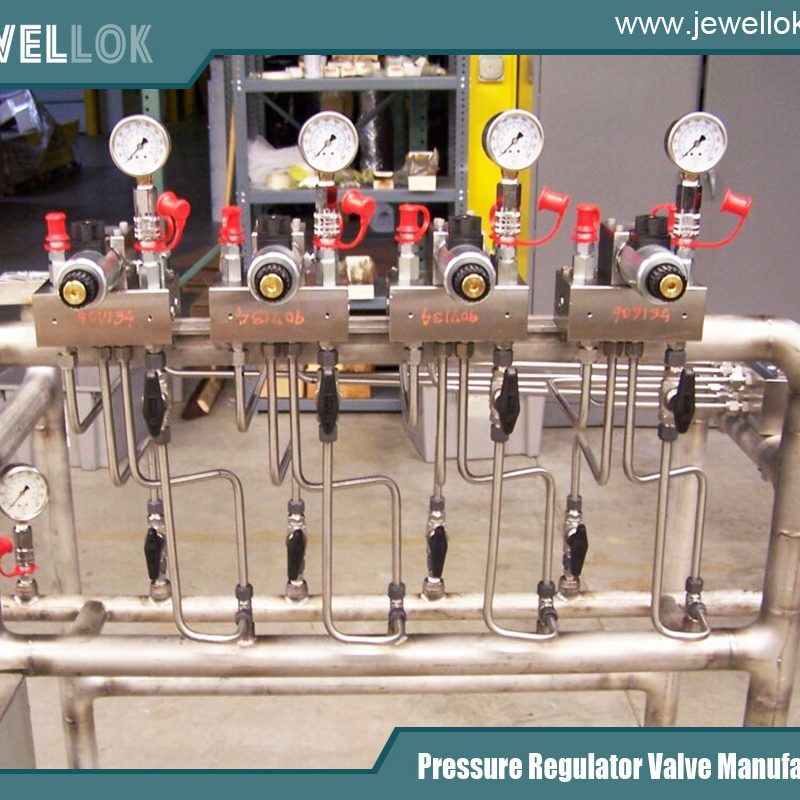
A Comprehensive Analysis of Parameter Selection for Pressure Reducing Valves in High-Flow Working Conditions
- Pressure Regulator Valve Manufacturer
- 1 1 2 gas pressure regulator, 1 2 gas regulator, 1 2 propane regulator, 1/2 gas pressure regulator, 12v electric valve, adjustable propane pressure regulator, argon gas pressure regulator, electric water valve, gas regulator, high pressure argon regulator, high purity pressure reducing valves manufacturer, high purity pressure reducing valves manufacturer in china, high purity regulator, high-flow pressure reducing valves, high-flow pressure reducing valves campany, high-flow pressure reducing valves manufacturer, Hydraulic Pressure Reducing Valves, industrial regulators, lab fittings exporter, large-flow single-gauge pressure reducing valves, pressure reducing valves, pressure reducing valves manufacturer, pressure regulator, pressure safety valve vs relief valve, propane pressure regulator valve, relief valve and safety valve difference, safety valve vs relief valve, semiconductor gas, single-gauge pressure reducing valves, what is a flame arrestor
- No Comments
A Comprehensive Analysis of Parameter Selection for Pressure Reducing Valves in High-Flow Working Conditions
In various industrial and civil systems, high-flow working conditions are widely present, such as in large-scale chemical production, urban water and gas supply, thermal power generation, and other fields. As a key device for regulating fluid pressure, the reasonable selection of a pressure reducing valve plays a crucial role in the stable operation of the system, efficient production, and safety guarantee. In high-flow working conditions, once the pressure reducing valve is improperly selected, it may lead to serious consequences such as excessive pressure fluctuations, uneven flow distribution, equipment damage, and even safety accidents. Therefore, it is of great practical significance to deeply explore how to reasonably select the caliber, material, and other relevant parameters of the pressure reducing valve according to specific high-flow working conditions.

Clarify Working Condition Parameters
(A) Flow Parameters
- Maximum Flow ( Q_{max}): It refers to the maximum fluid flow that may occur in a specific working condition. This is one of the key bases for selecting the caliber of the pressure reducing valve. For example, during the peak water consumption period of the urban water supply system, the water consumption will reach the maximum value, and the flow rate at this time is the maximum flow. Accurately measuring or estimating the maximum flow can ensure that the selected pressure reducing valve can meet the flow requirements of the system under the most severe working conditions. It can be determined through historical data statistics, theoretical calculations (based on the system’s design capacity, equipment operation parameters, etc.), and experience reference from similar projects.
- Minimum Flow ( Q_{min}): It is the minimum flow that may occur during the normal operation of the system. Although the pressure reducing valve is mainly designed for high-flow working conditions, its stable working performance under low-flow conditions also needs to be considered. For example, at night, the water consumption of the urban water supply system will drop significantly, and the flow rate at this time is the minimum flow. If the pressure reducing valve cannot work stably under the minimum flow, problems such as pressure fluctuations and noise may occur. Determining the minimum flow helps to judge whether the flow adjustment range of the pressure reducing valve meets the system requirements.
- Flow Fluctuation Range: That is, the difference between the maximum flow and the minimum flow and the change frequency. In working conditions with large flow fluctuations, higher requirements are placed on the response speed and adjustment accuracy of the pressure reducing valve. For example, in the chemical production process, due to changes in the production process, the fluid flow may fluctuate frequently and significantly. Understanding the flow fluctuation range can help select a pressure reducing valve with appropriate dynamic performance to ensure stable pressure output even when the flow changes.
(B) Pressure Parameters
- Inlet Pressure ( P_{1}): The fluid pressure at the inlet of the pressure reducing valve. It is necessary to clarify the normal operating range of the inlet pressure of the system, including the maximum and minimum values. The accurate determination of the inlet pressure is crucial for selecting the pressure resistance grade of the pressure reducing valve. If the inlet pressure exceeds the rated pressure resistance value of the pressure reducing valve, potential safety hazards such as valve damage and leakage may occur. For example, in a natural gas pipeline, the pressure at different stations may vary, and it is necessary to accurately grasp the inlet pressure situation at each station.
- Outlet Pressure ( P_{2}): The stable pressure value required at the outlet of the pressure reducing valve. This depends on the needs of downstream equipment or processes. Different industrial processes and civil facilities have different requirements for the outlet pressure. For example, chemical reaction equipment may require a precisely stable low-pressure environment, while building fire protection systems have specific standard requirements for the outlet pressure. Ensuring that the pressure reducing valve can stably adjust the inlet pressure to the required outlet pressure is an important goal of the selection.
- Allowable Pressure Fluctuation Range: It refers to the allowable fluctuation range of the outlet pressure under normal working conditions. For some systems with extremely high requirements for pressure stability, such as the gas supply system of an electronic chip manufacturing workshop, the allowable pressure fluctuation range is very small, generally within ±0.01MPa. For some ordinary industrial systems, the allowable pressure fluctuation range may be relatively large. Clarifying the allowable pressure fluctuation range helps to select a pressure reducing valve with appropriate pressure regulation accuracy.
(C) Medium Characteristics
- Corrosiveness: If the medium is corrosive, such as acid and alkali solutions in the chemical production process, it is necessary to select a corrosion-resistant material for the pressure reducing valve. For strong acidic media, 316L stainless steel is a commonly used choice. It contains a relatively high content of molybdenum elements, which can effectively resist the corrosion of chloride ions, etc. For alkaline media, certain nickel-based alloys may have better corrosion resistance. Selecting an inappropriate material will lead to the corrosion of internal components of the pressure reducing valve, shorten the service life of the valve, and even cause safety accidents such as leakage.
- Viscosity: High-viscosity media, such as lubricating oil, syrup, etc., will generate relatively large resistance when flowing through the pressure reducing valve. For high-viscosity media, it is necessary to select a valve body and valve core structure with a larger flow area to ensure that a sufficient flow rate can pass through. For example, in the lubricating oil conveying system, a pressure reducing valve with a large-caliber flow channel and a special valve core design can be selected to reduce the pressure loss. At the same time, the influence of the medium viscosity on the sealing performance of the valve also needs to be considered, and an appropriate sealing material should be selected.
- Particle Impurity Content: When the medium contains particle impurities, such as sewage in the sewage treatment system, gas containing dust, etc., the pressure reducing valve is prone to wear and blockage. To deal with this situation, a pressure reducing valve with an internal filter screen or a wear-resistant valve core and valve seat material can be selected. In a sewage treatment plant, a pressure reducing valve with a coarse filter screen is often used to first filter the large particle impurities in the sewage to protect the internal structure of the valve. In addition, the pressure reducing valve also needs to be regularly cleaned and maintained to ensure its normal operation.
Selection of Pressure Reducing Valve Caliber
(A) Flow Coefficient (Cv Value) Method
- Definition and Calculation of Cv Value: The flow coefficient Cv value represents the flow capacity of the valve under specific conditions. Its definition is: when the valve is fully open, the pressure difference across the valve is 1psi (pound-force per square inch), and the medium is normal temperature water, the number of gallons of flow passing through the valve per minute. The calculation formula for the Cv value is Cv = \frac{Q\sqrt{SG}}{\sqrt{\Delta P}}, where Q is the flow rate ( m^{3}/h), SG is the relative density of the medium (compared with water), and \Delta P is the pressure difference before and after the valve (MPa). For example, for a working condition with a flow rate of 100 m^{3}/h, a medium relative density of 0.8, and a pressure difference before and after the valve of 0.2MPa, the Cv value can be calculated.
- Selecting the Caliber According to the Cv Value: Pressure reducing valves of different calibers have different Cv value ranges. The caliber that matches the calculated Cv value can be found by referring to the product samples of the pressure reducing valve or relevant standards. Generally, the caliber of the pressure reducing valve with a Cv value slightly larger than the calculated value should be selected to ensure that the valve still has a certain margin under the maximum flow working condition, avoiding the valve from being in the full-open limit state, which affects the adjustment performance and service life. At the same time, the flow fluctuation situation in the actual working condition also needs to be considered, and an appropriate margin should be left.
(B) Empirical Formula Method
- Common Empirical Formulas: In some engineering practices, empirical formulas can also be used to initially estimate the caliber of the pressure reducing valve. For liquid media, a commonly used empirical formula is D=\sqrt{\frac{4Q}{\pi v}}, where D is the valve caliber (mm), Q is the flow rate ( m^{3}/h), and v is the flow velocity of the medium in the valve (m/s). For gas media, the empirical formula is D=\sqrt{\frac{4QZRT}{\pi vP}}, where Z is the gas compression coefficient, R is the gas constant, T is the gas temperature (K), and P is the gas pressure (MPa). These empirical formulas are based on certain engineering practices and assumptions, and the calculation results are for reference only.
- Precautions for Applying the Formulas: When using the empirical formulas, the parameter values in the formulas need to be reasonably determined. For example, the selection of the medium flow velocity v needs to consider factors such as the nature of the medium, the material of the pipeline, and the system requirements. For liquid media, the general flow velocity value is between 1 – 3m/s; for gas media, the flow velocity value varies according to factors such as the gas type and pressure, usually between 10 – 30m/s. At the same time, due to the limitations of the empirical formulas, the calculation results should be comprehensively judged and adjusted in combination with the actual working conditions and other factors.
(C) Consideration Factors
- Future Flow Growth: When selecting the caliber of the pressure reducing valve, it is necessary to not only meet the current flow requirements but also consider the possible future flow growth of the system. For example, in urban planning, with the increase in population and economic development, the flow requirements of the water supply and gas supply systems may gradually increase. Therefore, when selecting the type, an appropriate margin can be reserved, and a pressure reducing valve with a slightly larger caliber can be selected to avoid the frequent replacement of equipment due to future flow growth. Generally, according to the development plan and prediction of the system, a flow growth margin of 10% – 30% can be reserved.
- Resistance of the Pipeline System: The resistance of the pipeline system where the pressure reducing valve is located will also affect the selection of the caliber. If the resistance of the pipeline system is large, in order to ensure that a sufficient flow rate can pass through, it may be necessary to select a pressure reducing valve with a larger caliber. When calculating the resistance of the pipeline system, factors such as the length of the pipeline, the diameter of the pipeline, the roughness, and the number of pipe fittings need to be considered. For example, in a long-distance water transmission pipeline, due to the large pipeline resistance, it may be necessary to select a pressure reducing valve with a larger caliber than the theoretically calculated one to ensure that end users can obtain sufficient water volume and pressure.
Selection of Pressure Reducing Valve Material
(A) Metal Materials
- Stainless Steel: It has good corrosion resistance, strength, and toughness, and is widely used in various corrosive media and occasions with high hygiene requirements. 304 stainless steel is suitable for general corrosive media, such as the water and gas transmission in the food and beverage industry; 316L stainless steel is more resistant to strong corrosive media, such as the acid and alkali environment in the chemical industry. Its advantages are strong corrosion resistance, long service life, and good hygiene performance; the disadvantage is that the cost is relatively high. In the purified water system of a pharmaceutical factory, 316L stainless steel pressure reducing valves are often used to ensure that the water quality is not contaminated.
- Copper and Copper Alloys: They have good thermal conductivity, corrosion resistance, and processing performance, and are often used in occasions with medium and low pressure and non-strong corrosive media, such as the water supply and heating systems of civil buildings. Brass (copper-zinc alloy) has a relatively low cost and is widely used; bronze (copper-tin alloy) has better wear resistance and corrosion resistance. Its advantages are relatively low cost, easy processing, and good thermal conductivity; the disadvantage is that the strength is relatively low, and the corrosion resistance is limited in some strong corrosive media. In the household tap water pipeline, brass pressure reducing valves are commonly used.
- Carbon Steel: It has a low price and high strength, but poor corrosion resistance. It is generally used in non-corrosive media or occasions with anti-corrosion measures. For example, in the industrial gas transmission pipeline, after anti-corrosion treatment, a carbon steel pressure reducing valve can be used. Its advantages are low cost and high strength; the disadvantage is that it is easy to rust and corrode and requires regular maintenance and anti-corrosion treatment. In some industrial projects with strict cost control, if the medium is not highly corrosive, a carbon steel pressure reducing valve with an anti-corrosion coating treatment can be used.
(B) Non-Metal Materials
- Engineering Plastics: Such as polytetrafluoroethylene (PTFE), polypropylene (PP), etc., have good corrosion resistance, chemical resistance, and low friction coefficient, and are often used in occasions with strong corrosiveness and not high temperatures. PTFE has excellent tolerance to almost all chemical substances and can be used in extreme corrosive media such as strong acids and alkalis. Its advantages are extremely strong corrosion resistance, light weight, and low cost; the disadvantage is that the strength is relatively low and the high-temperature resistance performance is limited. In some small-scale chemical experimental devices, PTFE pressure reducing valves may be used.
- Rubber: It is mainly used for sealing parts and some occasions with low pressure and not strong corrosiveness, such as the sealing part of a household gas pressure reducing valve. Rubber has good elasticity and sealing performance and can effectively prevent the leakage of the medium. Different types of rubber are suitable for different media and working conditions. For example, nitrile rubber has good oil resistance and is often used in the fuel system; ethylene propylene diene monomer (EPDM) rubber has good weather resistance and chemical resistance and can be used for the sealing of water and some weakly corrosive gases. Its advantages are good sealing performance, low cost, and convenient installation; the disadvantage is that it is easy to age and has a limited service life.
(C) Selection According to the Medium and Working Conditions
- Corrosive Media: As mentioned above, for strong corrosive media, corrosion-resistant materials such as stainless steel (such as 316L) and engineering plastics (such as PTFE) should be preferentially selected. In the acidic plating solution conveying system of an electroplating workshop, it is necessary to use corrosion-resistant materials to prevent the pressure reducing valve from being corroded and damaged and ensure the normal operation of production. For medium corrosive media, appropriate stainless steel or copper alloy materials can be selected according to the cost and specific working conditions.
- High-Temperature Media: When the medium temperature is high, it is necessary to select a high-temperature resistant material. For the steam system, a heat-resistant steel material pressure reducing valve, such as a chromium-molybdenum alloy steel, can be selected. This material can still maintain good strength and corrosion resistance at high temperatures. At the same time, the influence of high temperature on the sealing material also needs to be considered, and a high-temperature resistant sealing material, such as a graphite sealing element, should be selected. In the steam pipeline of a thermal power plant, a chromium-molybdenum alloy steel pressure reducing valve is often used.
- Food and Pharmaceutical Industry: In the food and pharmaceutical industries, extremely high requirements are placed on the hygiene performance of the pressure reducing valve materials. Generally, 304 stainless steel or copper materials with special treatment are selected to ensure that they will not cause pollution to the products. At the same time, the surface treatment process is also very important, requiring a smooth surface and easy cleaning, in line with relevant food hygiene standards and pharmaceutical industry specifications. In the batching system of a beverage production factory, the pressure reducing valves used must meet the food hygiene grade standards.
Selection of Other Relevant Parameters
(A) Structural Type
- Direct Acting Type: It has a simple structure, consisting of a valve core, a spring, a diaphragm, etc., and adjusts the outlet pressure by relying on the balance between the inlet pressure and the spring force. Its advantages are simple structure, low cost, and sensitive action; the disadvantage is that the adjustment accuracy is relatively low, and it is suitable for occasions with small pressure and flow fluctuations and not high accuracy requirements, such as the simple pressure reducing system of small industrial equipment. In the pressure reducing device of a small air compressor, a direct acting pressure reducing valve is often used.
- Pilot Operated Type: It controls the action of the main valve through the pilot valve, has high adjustment accuracy, and can adapt to large pressure and flow changes. The pilot operated pressure reducing valve consists of a main valve and a pilot valve, and the pilot valve controls the opening degree of the main valve according to the change of the outlet pressure. Its advantages are high adjustment accuracy, good pressure stabilization performance, and the ability to adapt to high-flow and high-pressure difference working conditions; the disadvantage is that the structure is complex and the cost is high. In large-scale chemical production devices, due to the extremely high requirements for pressure control accuracy, a pilot operated pressure reducing valve is often used.
- Piston Type: It uses a piston as the driving component of the valve core and is suitable for high-pressure and high-flow occasions. In the piston type pressure reducing valve, the piston moves in the cylinder body and realizes pressure reduction by changing the throttling area. Its advantages are the ability to withstand high pressure and large flow, and good sealing performance; the disadvantage is that the structure is relatively complex and the manufacturing process requirements are relatively high. In high-pressure gas transmission pipelines, piston type pressure reducing valves are widely used.
(B) Adjustment Accuracy
- Accuracy Grade Classification: The adjustment accuracy of the pressure reducing valve is usually expressed by the fluctuation range of the outlet pressure and can be divided into different accuracy grades, such as ±0.5%, ±1%, ±2%, etc. The higher the accuracy grade, the smaller the fluctuation range of the outlet pressure and the better the pressure stability. For example, in the gas supply system of some precision instruments, a pressure reducing valve with an accuracy grade of ±0.5% may be required to ensure the normal operation of the instruments.
- Selection According to Working Condition Requirements: For systems with high requirements for pressure stability, such as the electronic chip manufacturing and precision chemical industries, a pressure reducing valve with high adjustment accuracy should be selected; for some ordinary industrial systems and civil facilities, such as the general building water supply and heating systems, a pressure reducing valve with relatively low adjustment accuracy.
For more about a comprehensive analysis of parameter selection for pressure reducing valves in high-flow working conditions, you can pay a visit to Jewellok at https://www.jewellok.com/ for more info.
Recent Posts
How to Safely Operate a TMA Gas Changeover Manifold
How to Choose an Ultra High Purity CO2 Pressure Reducing Valve
The Top High-Pressure Argon Gas Regulator Manufacturer in China
How to Choose a Gas Cylinder Manifold System
Tags
Recommended Products
-
JR1300 Series Ultra High Purity Single Stage Regulator High Flow Line Regulator For Ultra High Purity Intermediate Flow
-
Medical Oxygen Single Stage Manual Gas Changeover Manifold Panel High-Purity Two-Stage Manual Gas Manifold Gas Pressure Control Panels
-
Fully Automated Gas Cabinet For Precise UHP Gas Delivery And High Purity Gas Delivery Systems JW-300-GC
-
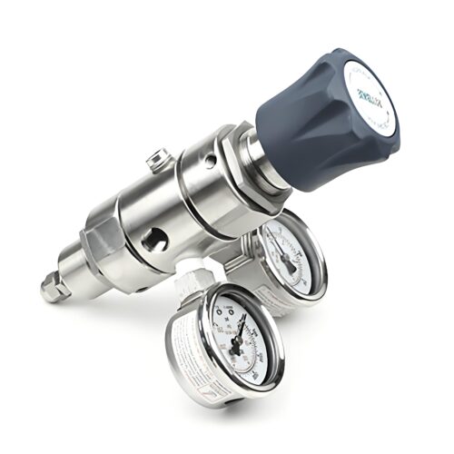
DPR1 Ultra High Purity Two Stage Dual Stage Pressure Reducing Regulator Semiconductor Grade Regulators
-
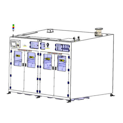
Scrubber Gas Cabinet Scrubber Tail Gas Treatment Cabinet Vent Gas Scrubber System Heat-Filter Burn Box Gas Scrubber/Abatement System
-
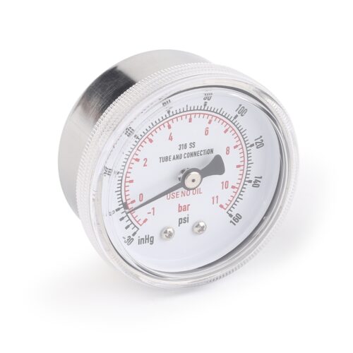
Ultra High Purity Pressure Gauge For Laboratory And Semiconductor JR Series
-
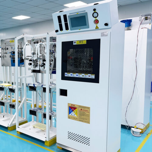
Semi Automatic Gas Cabinet Gas Panels High Purity Gas Delivery Systems JW-200-GC
-
Ultra High Purity Oxygen Pressure Gauge For Semiconductor Gases JG Series Pressure Instruments For Semiconductor Manufacturing
