Valves Manufacturer Tel: +86 13380377051

How to Select the Right Valve Manifold Box for Your Application
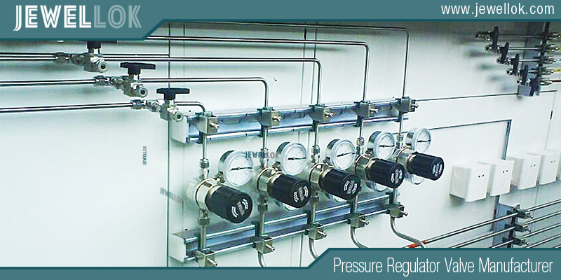
In the intricate world of industrial fluid control—spanning process automation, chemical handling, water treatment, and manufacturing—precision, reliability, and safety are paramount. At the heart of many sophisticated fluid control systems lies a critical, yet sometimes under-specified component: the valve manifold box. Also known as a manifold enclosure, valve link, or sometimes simply a manifold assembly, this unit is far more than a mere junction block. It is the strategic interface between your field-mounted process valves (like control valves, solenoid valves, or actuated ball valves) and your central control system.
Selecting the optimal valve manifold box is not a trivial exercise in catalog shopping. A poor choice can lead to system downtime, hazardous leaks, difficult maintenance, and ultimately, increased total cost of ownership. This technical article provides a systematic framework for evaluating and selecting the right manifold box, ensuring it enhances—rather than compromises—your application’s performance.
Deconstructing the Valve Manifold Box: Core Function and Anatomy
Before selection, one must understand its purpose. A valve manifold box serves three primary functions:
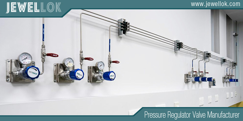
- Interface and Simplification: It replaces complex networks of individual tubing runs from each valve to the control room with a single, multi-conductor cable or hose bundle connected to a centralized manifold. This drastically simplifies installation, reduces potential leak points, and improves system clarity.
- Actuation and Control: It houses the pneumatic or electrical components (solenoid valves, pressure regulators, gauges, switches) that supply motive power and control signals to the field valves. It translates the low-energy electrical signal from a PLC/DCS into the high-power pneumatic or electrical action required to move an actuator.
- Protection and Safety: The enclosure safeguards sensitive components from environmental hazards (dust, water, corrosive atmospheres) and provides a degree of personnel protection from moving parts and live electrical terminals.
A typical manifold box consists of:
- Enclosure: The physical housing (metal or plastic) with a specified Ingress Protection (IP) or NEMA rating.
- Manifold Baseplate: The machined block (often aluminum or stainless steel) that provides the porting for pneumatic supply, exhaust, and multiple output connections to field devices.
- Valve Islands/Valves: The solenoid valves (often banked together as a “valve island”) mounted onto the baseplate. These can be individual valves or modular, single-piece manifolds.
- Electrical Connections: Terminal blocks, multi-pin connectors (e.g., M12, M23), or cable glands for power and signal input.
- Ancillary Components: FRL units (Filter, Regulator, Lubricator), pressure gauges, flow controls, and diagnostic LEDs.
The Selection Framework: A Step-by-Step Guide
Step 1: Define the Core Application Requirements
This is the foundation. Vague requirements guarantee a suboptimal selection.
- Valve/Actuator Type & Quantity: What are you controlling? Pneumatic diaphragm control valves, quarter-turn ball/butterfly valve actuators, hydraulic cylinders, or electric actuators? How many devices? This defines the number of output ports needed (e.g., 4/2-way, 5/2-way, or 5/3-way solenoid valve functions per actuator).
- Media: What is the control medium? Clean, dry instrument air? Aggressive natural gas? Hydraulic oil? This dictates material compatibility (e.g., Buna-N seals for standard air, Viton for hydrocarbons, stainless steel for corrosive media).
- Pressure and Flow Requirements: What is the required supply pressure (e.g., 80-120 psi / 5.5-8 bar)? What is the actuator volume and required cycle speed? This determines the required orifice size (Cv value) of the solenoid valves and the internal port sizing of the manifold. Undersized ports will slow actuator response.
- Duty Cycle and Reliability: Is it a continuously modulating application, a high-speed on/off cycle (e.g., packaging machine), or a seldom-used safety shut-off? Duty cycle influences valve choice (poppet vs. spool) and expected service life.
Step 2: Specify the Operational Environment
The environment dictates the enclosure’s protective duty and may influence internal component selection.
- Ingress Protection (IP Rating) or NEMA Rating: This is non-negotiable.
- IP65/66 / NEMA 4, 4X: Protection against low-pressure water jets and dust. Standard for most indoor industrial settings (factory floors).
- IP67 / NEMA 6: Protection against temporary immersion. For washdown areas (food & beverage, pharmaceuticals) or outdoor locations subject to flooding.
- IP68/69K / NEMA 6P: Protection against prolonged immersion (IP68) or high-pressure, high-temperature washdowns (IP69K). Critical for harsh hygienic environments.
- Hazardous Areas: If located in a potentially explosive atmosphere (Zone 1/21 or Zone 2/22), the entire assembly—enclosure, solenoid valves, and connectors—must be certified for the zone (e.g., ATEX, IECEx, UL Class I Div 2). This often requires explosion-proof (Ex d) or intrinsically safe (Ex i) designs.
- Ambient Conditions: Extreme temperatures (arctic cold or foundry heat), UV exposure (outdoors), or corrosive chemicals (marine, chemical plants) will influence material choice (stainless steel 316L vs. painted aluminum vs. fiberglass-reinforced polyester) and seal materials.
Step 3: Choose the Valve Technology and Configuration
The solenoid valve is the heart of the manifold.
- Valve Type:
- Poppet Valves: Robust, tolerant of slightly dirty air, good for on/off applications. Can be noisier and require higher pilot power.
- Spool Valves: Excellent for high cycling, low power consumption, and sometimes proportional control. Require cleaner air.
- Operating Principle:
- Direct-Acting: Solenoid force directly opens/closes the orifice. Typically used for small orifice sizes.
- Pilot-Operated: Uses line pressure to shift the main spool/poppet. Allows for large flow rates with a small, energy-efficient solenoid. Most common for industrial valve manifolds.
- Voltage and Electrical Connection: Match plant standards (24V DC is most common for control, 120V AC may be used in some regions). Choose the connection type:
- Individual Conduit Entries: Traditional but time-consuming to wire.
- Pre-wired Multi-pin Connector (M12, M23): The modern standard. Enables plug-and-play installation, drastically reducing commissioning and changeover time. Choose the pinout (e.g., 4-pin for single solenoid, 7-pin for double solenoid with feedback).
- Diagnostics and Intelligence: Modern “smart” manifolds offer embedded sensors for:
- Individual Valve Feedback: Electrical confirmation (PNP/NPN) or even pressure sensing to confirm valve spool position.
- Pressure Monitoring: On-board sensors for supply or output pressure.
- Communication Buses: Integration via PROFINET, EtherNet/IP, PROFIBUS, or IO-Link. This allows for centralized diagnostics, predictive maintenance alerts, and parameter setting from the control room.
Step 4: Consider Integration and Lifecycle Factors
Think beyond the initial purchase order.
- Ease of Installation and Maintenance:
- Can the enclosure be mounted easily? Does it have clear mounting points?
- Are components accessible? Can a single solenoid valve be replaced without dismantling the entire bank or disconnecting all tubing? Modular manifolds excel here.
- Is the internal layout logical, with clear labeling?
- Scalability and Modularity: Is the design modular? Can you easily add another bank of valves in the field if the process expands? Some systems allow “adding on” manifolds to a common supply rail and communication backbone.
- Supply Air Preparation: Should an integrated FRL (Filter, Regulator, Lubricator) unit be specified? Always filter and regulate air at the point of use. Lubrication is application-dependent (avoid it in food, pharmaceutical, or where lubricant can contaminate process media).
- Vendor Support and Global Standards: Does the supplier offer technical support, CAD drawings, and a reliable supply chain? Are components conformant to international standards (ISO, CE)? This is crucial for long-term maintainability and spare parts availability.
Application-Specific Considerations: Case Studies
- Process Plant (Continuous Control): Focus on reliability and diagnostics. A stainless-steel (NEMA 4X) enclosure with IP65-rated, pilot-operated spool valves is typical. IO-Link communication for valve-level diagnostics can preempt failures. 5/3-way or proportional valves might be needed for specific control functions.
- Factory Automation / Packaging (High-Speed Discrete): Speed, compactness, and connectivity are key. A plastic or aluminum enclosure with a high-flow, pilot-operated valve bank and a single M23 connector for power and signals minimizes machine panel space and wiring. Poppet valves may be chosen for durability in less-than-perfect air conditions.
- Hygienic / Washdown (Food, Beverage, Pharma): Material and cleanability are paramount. A polished 316L stainless steel enclosure with IP69K rating is standard. Valves should have a smooth, crevice-free external design. Internal materials (seals, solenoids) must withstand frequent cleaning with caustic or acidic agents. Often specified with quick-disconnect fittings for hose connections.
- Mobile Equipment (Agriculture, Construction): Ruggedness and resistance to vibration/shock are critical. Heavy-duty metal enclosures with superior sealing (IP67) are needed. Valves should be specifically tested for vibration resistance. Hydraulic manifolds in this sector require careful attention to pressure ratings and port types (SAE, BSPP).
Conclusion
Selecting the right valve manifold box is a systems engineering task. It requires moving from a vague notion of “needing a box for some valves” to a precise specification document. By rigorously following the framework outlined—starting with a deep understanding of the application, defining the environmental challenges, selecting the appropriate valve technology, and factoring in total lifecycle costs—you transform the manifold box from a potential point of failure into a cornerstone of system reliability, efficiency, and safety.
The most cost-effective choice is rarely the cheapest unit on the shelf. It is the one meticulously matched to your system’s technical demands and operational reality, delivering uninterrupted service and simplifying maintenance for years to come. Invest time in the selection process; your future self—and your plant’s operational metrics—will thank you for it.
For more about how to select the right valve manifold box for your application, you can pay a visit to Jewellok at https://www.jewellok.com/ for more info.
-

Line And Panel Mounting Adjustable Low Pressure Propane And Nitrogen Pressure Regulator JSR-3L & JSR-3LP Series
-

Semi Automatic Gas Cabinet Gas Panels High Purity Gas Delivery Systems JW-200-GC
-

Integrated Gas System (IGS) Modular Integrated Gas Systems (TMS) Integrated Gas Supply System For Semiconductor And Laboratory
-

High Purity High Pressure Gas Cylinder Pressure Regulators Pressure Reducing Valve JSR-1E Series
-

Single Stage Wall And Cabinet Mounting Pressure Control Panels JSP-2E Series For High Purity Gases
-

Stainless Steel High Purity High Temperature Pneumatic Actuated Ball Valves JBV2 Series
-

Semiconductor High Purity High Pressure Specialty Gas Bottle Gas Cylinder Storage Cabinet And Gas Pressure Regulating Cabinet
-

Hydrogen Manifold Argon Gas Manifold System Oxygen Manifold Propane Gas Manifold With Valves In Gas Manifold Changeover System