Blog
Jewellok is a professional pressure regulator and valve manufacturer and supplier.
Optimal Design of the Internal Structure of High-Flow Pressure Reducing Valves to Prevent Cavitation and Water Hammer
- Pressure Regulator Valve Manufacturer
- adjustable propane regulator, adjusting propane regulator, automatic switching valve, bcf connector, block & bleed valve, chinese propane gas cylinder, diaphragm suppliers, diaphram valve, double block & bleed, double block and bleed valve, double block bleed valve, excess flow valve, fusible plug, gas regulator, high flow co2 regulator, high pressure flexible hose, high-flow pressure reducing valves, high-flow pressure reducing valves campany, high-flow pressure reducing valves factory, high-flow pressure reducing valves manufacturer, high-flow pressure reducing valves supplier, how a solenoid valve works, how does a needle valve work, hydraulic regulator, industrial grade purity, low pressure regulator, o ring face seal fittings, pressure relief valve vs safety relief valve, quick connect, quick connect valve, relief vs safety valve, safety valve and relief valve, solenoid valve for ammonia gas 1 inch pipe, stainless pressure regulator, ultra high purity, water solenoid valve 24v, what is a gas pressure regulator
- No Comments
Optimal Design of the Internal Structure of High-Flow Pressure Reducing Valves to Prevent Cavitation and Water Hammer
In industrial fluid conveying, water supply and drainage, and other systems involving the transmission of high-flow media, the pressure reducing valve is a key device to ensure the stability of the system pressure. However, when high-flow media pass through the pressure reducing valve, cavitation and water hammer phenomena are likely to occur. Cavitation will lead to the corrosion and wear of the valve body and internal components, reducing the service life of the equipment; water hammer will cause pipeline vibration, noise, and even serious consequences such as pipeline rupture and equipment damage. Therefore, optimizing the internal structure of the high-flow pressure reducing valve to effectively prevent cavitation and water hammer phenomena is of great practical significance.

Generation Mechanisms of Cavitation and Water Hammer
1. Generation Mechanism of Cavitation
When high-flow media flow through the pressure reducing valve, near components such as the valve core and valve seat, due to the sharp change in flow velocity, the local pressure drops rapidly. When the pressure drops to the saturated vapor pressure of the medium at this temperature, the liquid begins to vaporize, forming a large number of tiny bubbles. These bubbles flow with the liquid to the high-pressure area, and under the action of high pressure, they collapse rapidly, generating extremely high local pressure and temperature. Repeatedly acting on the metal surface, it causes fatigue damage to the material and forms cavitation pits, which is the generation process of the cavitation phenomenon.
2. Generation Mechanism of Water Hammer
In a high-flow system, when situations such as the sudden opening or closing of the pressure reducing valve, or the rapid operation of pipeline valves occur, the flow velocity of the medium will change sharply within a short period of time. According to the momentum theorem, the sudden change in flow velocity will cause a change in the momentum of the medium, thus generating a huge impact force. This impact force is like a hammer striking the pipeline, forming the water hammer phenomenon. The pressure fluctuation generated by the water hammer can reach several times or even dozens of times the normal working pressure, causing great harm to the pipeline and equipment.
Internal Structure Design of High-Flow Pressure Reducing Valves to Prevent Cavitation
1. Optimization of the Valve Body Flow Channel Structure
To reduce the local resistance of the medium flowing through the pressure reducing valve and prevent the pressure from dropping sharply due to the sudden change in flow velocity, the flow channel of the valve body should adopt a streamlined design. Avoid structures such as sharp corners, sudden contractions, or expansions. For example, adopt a gradually shrinking and expanding flow channel form to enable the medium to pass through the pressure reducing valve smoothly and reduce the pressure loss. At the same time, increase the radius of curvature of the flow channel to reduce the degree of turbulence of the medium flow, thereby reducing the possibility of cavitation occurrence.
2. Improvement of the Valve Core Structure
- Multi-stage Pressure Reducing Valve Core: Adopt a multi-stage pressure reducing valve core structure, decomposing the original single-stage pressure reducing process into multiple stages. In this way, the pressure difference of each pressure reducing stage can be reduced, avoiding the occurrence of cavitation due to too low local pressure. For example, by setting multiple pressure reducing steps, the pressure of the medium can be reduced gradually, reducing the probability of bubble generation.
- Special-shaped Valve Core: Design a valve core with a special shape, such as streamlined, parabolic, etc., to improve the flow field distribution around the valve core. Enable the medium to flow more uniformly when flowing through the valve core, reducing the formation of vortices and low-pressure areas, and thus suppressing the occurrence of cavitation.
3. Selection of Materials for Flow Components
Select materials with good cavitation resistance to manufacture the flow components of the pressure reducing valve, such as stainless steel, titanium alloy, etc. These materials have high strength and hardness and can withstand the impact force and corrosion effect generated by cavitation. At the same time, the surface treatment process is also crucial. Methods such as spraying wear-resistant and corrosion-resistant coatings and surface hardening treatment can be adopted to further improve the cavitation resistance of the flow components.
Internal Structure Design of High-Flow Pressure Reducing Valves to Prevent Water Hammer
1. Design of the Slow Closing Mechanism
Set a slow closing mechanism inside the pressure reducing valve. When the valve needs to be closed in the system, the slow closing mechanism can make the valve core close slowly. For example, adopt a hydraulic damping device or a spring buffer structure to control the closing speed of the valve core and extend the time for the change of the medium flow velocity, thereby reducing the water hammer pressure. By reasonably adjusting the parameters of the slow closing mechanism, the water hammer pressure can be controlled within a safe range.
2. Design of the Pressure Buffer Chamber
Set a pressure buffer chamber inside the valve body. When the water hammer pressure is generated, the buffer chamber can absorb part of the pressure energy. The buffer chamber is connected to the main channel through small holes or throttling devices, enabling the medium to flow between the buffer chamber and the main channel during pressure fluctuations, playing a role in buffering the pressure. At the same time, the volume and structural parameters of the buffer chamber need to be accurately calculated and designed according to the flow rate, pressure, and other working conditions of the system to ensure its buffering effect.
3. Setting of Guide Vanes
Set guide vanes inside the valve body to guide the flow direction of the medium, enabling the medium to flow more smoothly during the opening and closing process of the valve. The guide vanes can disperse the flow velocity of the medium and reduce the impact force generated by the sudden change in flow velocity, thus reducing the possibility of water hammer occurrence. In addition, the shape and angle of the guide vanes need to be optimized according to the structure of the valve and the characteristics of the medium to achieve the best guiding effect.
Simulation and Verification of the Structure Design
1. Numerical Simulation
Use computational fluid dynamics (CFD) software to perform numerical simulations on the internal flow field of the optimized pressure reducing valve. By simulating the flow situation of the medium in the pressure reducing valve under different working conditions, analyze the pressure distribution, flow velocity distribution, and the generation trends of cavitation and water hammer. According to the simulation results, further adjust and optimize the internal structure parameters to ensure the effectiveness of the design scheme.
2. Experimental Verification
Manufacture a prototype of the pressure reducing valve and conduct relevant experimental tests. During the experiment, simulate the high-flow working conditions and measure parameters such as the pressure, flow rate, vibration, and noise of the pressure reducing valve under different working conditions. Through the analysis of the experimental data, verify the actual effect of the internal structure design on preventing cavitation and water hammer phenomena. At the same time, compare the numerical simulation results with the experimental data, and correct and improve the design scheme.

Conclusion
The problems of cavitation and water hammer of high-flow pressure reducing valves seriously affect the normal operation and service life of the equipment. By optimizing the internal structure of the pressure reducing valve, such as adopting a streamlined valve body flow channel, a multi-stage pressure reducing valve core, a slow closing mechanism, a pressure buffer chamber, and other structures, combining with reasonable material selection, and using means such as numerical simulation and experimental verification to optimize and improve the design scheme, the occurrence of cavitation and water hammer phenomena can be effectively prevented, and the operational stability and reliability of high-flow pressure reducing valves can be improved, providing a strong guarantee for the safe operation of industrial production and fluid conveying systems. In the future, with the continuous development of technology, it is necessary to further conduct in-depth research and exploration of more effective technologies for preventing cavitation and water hammer to meet the growing needs of the high-flow fluid control field.
For more about optimal design of the internal structure of high-flow pressure reducing valves to prevent cavitation and water hammer, you can pay a visit to Jewellok at https://www.jewellok.com/ for more info.
Recent Posts
Which Gas Pressure Regulator is Best for Laboratory Use?
Complete Guide to Choosing the Best High Pressure Nitrogen Gas Regulator
Tags
Recommended Products
-
Specialty Gas Valves Ultra High Purity Gas Valves Ultra High Purity Gas Cylinder Valves UHP Cylinder Valve Ultra High Purity Gas Regulator
-
Stainless Steel Ultra High Purity Mini Butt Weld Mini Tee Reducer MTRW Series Fittings
-
771LF Female Run Tee | Stainless Steel Tube Fitting Compression Fittings 1/4 In 3-Way Tee Female Run Tee
-
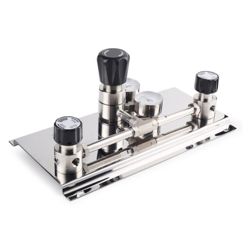
High Purity Semi-Auto Stainless Steel Changeover Manifold System, Nitrogen High Pressure Control Panel With Semiconductor Valve Manifold Box Diaphragm Valves
-
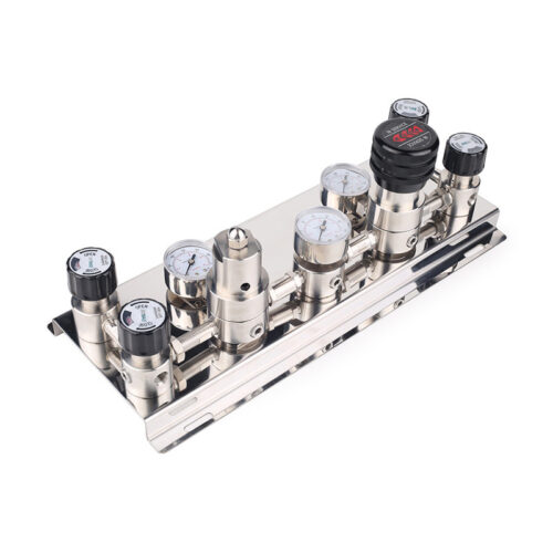
Automatic Gas Switchover System Automatic Switchover Manifold Automatic Gas Cylinder Switchover
-
Long Gland LG Series For Ultra High Purity Gas And Chemical Delivery Systems
-
765L Stainless Steel Union Elbow Reducing High Purity Fitting Tubing Extension Tubing Connection
-
Scrubber Gas Cabinet Scrubber Tail Gas Treatment Cabinet Vent Gas Scrubber System Heat-Filter Burn Box Gas Scrubber/Abatement System