Valves Manufacturer Tel: +86 13380377051
")
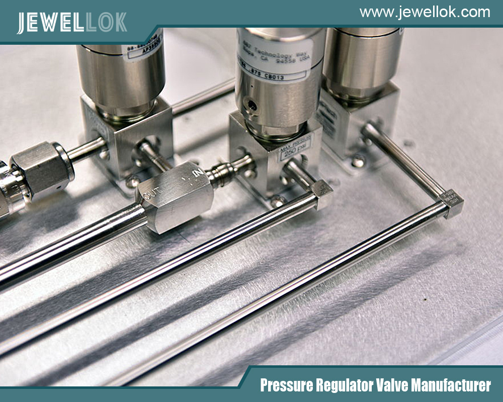
How Does A Low-Pressure Back Pressure Regulator Work?
In the intricate world of fluid control systems—encompassing gases and liquids—the primary regulator often gets the spotlight. These pressure-reducing regulators are the workhorses, taking a high, variable supply pressure and delivering a stable, lower pressure to a tool or process. But what happens at the end of the line? How do we protect sensitive upstream components from unexpected downstream surges, or maintain a precise pressure within a vessel or reactor? Enter the essential, yet often overlooked, component: the Low-Pressure Back Pressure Regulator (BPR). This device is not about reducing inlet pressure for a downstream application, but about controlling pressure by regulating the outlet or vent. This article delves into the mechanics, applications, and critical importance of how low-pressure back pressure regulators work to ensure system safety, precision, and efficiency.
The Fundamental Philosophy: Pressure Control by Managed Escape
To understand a Back Pressure Regulator, one must first flip the mental model of a traditional regulator. A typical pressure-reducing regulator is a normally-closed device. It opens to allow flow when downstream demand calls for it, controlling the pressure going forward.
A Back Pressure Regulator, in contrast, is a normally-open device. It is installed at the end of a process line, on a vessel outlet, or in a recirculation loop. Its primary function is to maintain a set pressure upstream of itself (i.e., in the system it is protecting) by opening to vent or bypass fluid once that set pressure is exceeded. It acts as a precisely tunable, automated relief valve.
The Core Mission:
- Maintain a Constant Upstream Pressure: Ensure a reactor, chromatographic column, distillation line, or fluidic manifold experiences a steady, bubble-tight pressure.
- Provide a System Seal: When system pressure is below the set point, the BPR remains closed, sealing the system from the vent or low-pressure drain.
- Relieve Excess Pressure: When upstream pressure rises above the set point (due to a pump stroke, thermal expansion, chemical reaction, or other process fluctuation), the BPR opens just enough to vent the excess, thereby protecting delicate upstream equipment and restoring the desired pressure.
- Manage Flow in Recirculation Loops: In closed-loop systems, it can maintain pressure on the suction side of a pump or within a loop by bypassing excess flow.
Anatomy of a Low-Pressure BPR: Key Components
While designs vary (piston vs. diaphragm), the soft-seated diaphragm-operated BPR is most common for low-pressure, high-sensitivity applications. Its components form a elegant feedback loop:
- Inlet Port (Upstream Pressure, P1): This is connected to the system needing protection. The pressure here (P1) is the force the regulator constantly monitors and controls.
- Outlet Port/Vent (Downstream Pressure, P2): This leads to a containment vessel, drain, flare, or low-pressure return line. The pressure here (P2) is typically atmospheric or a low, constant backpressure.
- Diaphragm (The Sensing Element): This flexible membrane is the “brain” of the device. One side is exposed to the upstream system pressure (P1) via a sensing passage. The other side is exposed to the Loading Force.
- Loading Mechanism (The Set Point Generator): This applies the opposing force that defines the set point. In low-pressure regulators, this is most often:
- Spring Loaded: A adjustable compression spring. Turning the adjustment knob compresses the spring, increasing the set point. This is simple and common for set points up to ~150 psi.
- Dome Loaded (for extreme precision): Uses a regulated gas pressure (e.g., from a separate air regulator) applied to a dome above the diaphragm. This provides a frictionless, perfectly balanced force, allowing for extremely precise and stable set points, especially in the 0-30 psi range.
- Valve Seat and Seal (The Control Element): Connected to the diaphragm via a stem. This seat rests against an orifice. When the seat lifts off the orifice, flow passes from the inlet (high-pressure side) to the outlet (low-pressure side).
- Body and Internal Passages: These direct the flow and ensure the diaphragm senses the true upstream pressure.
The Operational Cycle: A Step-by-Step Dance of Forces
The operation of a diaphragm-based BPR is a continuous ballet of force balance. Let’s trace the cycle:
- At Equilibrium (System Pressure = Set Point):
- Upstream system pressure P1 pushes on the underside of the diaphragm.
- The loading force (spring or dome pressure) pushes down on the top of the diaphragm.
- When P1 exactly balances the loading force, the diaphragm finds equilibrium. The valve seat is lightly closed against the orifice, creating a bubble-tight seal. No flow passes through the BPR. The system is sealed and pressurized at the desired set point.
- Pressure Rise (System Pressure > Set Point):
- A process event (e.g., a pump pulse, a heating phase, an injection) causes the upstream pressure P1 to increase.
- This increased pressure applies a greater upward force on the diaphragm, overpowering the downward loading force.
- The diaphragm flexes upward, pulling the valve stem and seat away from the orifice.
- This opens a flow path. Excess fluid (gas or liquid) escapes from the high-pressure upstream side, through the now-open orifice, to the low-pressure outlet/vent.
- This venting action begins to reduce the upstream pressure P1.
- Re-establishing Control:
- As P1 decreases due to venting, the upward force on the diaphragm lessens.
- The loading force now begins to overpower the diaphragm again, pushing it downward.
- The diaphragm moves down, guiding the valve stem and seat back toward the orifice, restricting the flow.
- At the precise moment P1 returns to the set point, the forces re-balance, and the seat re-seals. Venting stops.
This cycle happens continuously and often imperceptibly, with the diaphragm making micro-adjustments to maintain a rock-steady upstream pressure. The “low-pressure” aspect is critical here—the diaphragm can be large and very sensitive, allowing it to respond to minute pressure changes of fractions of a psi.
Why “Low-Pressure” Deserves Special Attention
While BPRs exist for all pressure ranges, low-pressure BPRs (typically operating in ranges from inches of water column up to 150 psi) present unique engineering challenges and require specific design features:
- High Sensitivity: The forces involved are small. A large, thin, responsive diaphragm is needed to sense tiny pressure variations.
- Precision Machining: Valve seats and orifices must be impeccably machined to achieve a bubble-tight seal at very low cracking pressures (the pressure at which the valve first opens).
- Minimal Hysteresis: The regulator should return to the same set point whether approached from a higher or lower pressure. This requires low-friction designs, often with rolling diaphragms or special guides.
- Materials Compatibility: In laboratory, food, beverage, or medical applications (common low-pressure arenas), wetted materials like 316L stainless steel, PTFE, and medical-grade elastomers are essential for purity and corrosion resistance.
Key Applications: Where Low-Pressure Back Pressure Regulators Are Indispensable
- Chromatography & Analytical Chemistry: In HPLC or GC systems, a BPR is placed after the chromatography column to maintain a constant, pulse-free pressure on the column, ensuring consistent retention times and peak shapes, regardless of downstream fluidic changes.
- Bioreactors & Fermenters: They maintain a precise, sterile headspace pressure of air or nitrogen (often 0.1-0.5 bar) to optimize cell growth and prevent contamination.
- Solvent Delivery & Flash Chromatography: Placed after the separation column, they provide consistent system backpressure to prevent solvent outgassing and ensure stable pump operation.
- Carbonated Beverage Dispensing (and similar): While not always called a BPR, the principle is identical. A regulator on a CO2 tank maintains pressure in the keg (the upstream system) by allowing gas to flow only when keg pressure drops below the set point.
- Pump Protection & Recirculation Loops: Installed on the discharge side of a positive displacement pump (like a gear pump), a BPR protects the pump and piping from dead-heading by bypassing excess flow when a downstream valve closes, maintaining a safe system pressure.
- Distillation & Condenser Pressure Control: In laboratory-scale distillation, a BPR on the condenser outlet can maintain a precise, sub-atmospheric pressure in the boiling flask to control boiling points.
- Gas Blanketing & Sparging: To maintain a protective inert atmosphere (N2, Ar) over a sensitive fluid in a tank at a very low positive pressure, a BPR on the tank vent ensures the blanket is maintained without over-pressurizing the vessel.
Selection and Sizing Considerations
Choosing the correct low-pressure BPR is vital:
- Set Pressure Range: Select a regulator whose adjustable range comfortably contains your required set point. Operating in the middle 50% of its range often yields best performance.
- Flow Capacity (Cv): You must know the expected maximum flow rate (in SCFM for gas, GPM for liquid) that the BPR might need to vent. The regulator must be sized with a Cv value high enough to pass this flow without causing an excessive pressure overshoot upstream. Undersizing is a common error.
- Fluid Compatibility: Material selection for the body, diaphragm, and seals must be compatible with the process fluid (gas or liquid) to avoid corrosion, degradation, or contamination.
- Accuracy & Sensitivity: Determine the required control tolerance. Dome-loaded regulators offer superior accuracy for the most demanding applications.
- Connections: Ensure port sizes and thread types (NPT, ISO, VCR) match the system.
Conclusion
The low-pressure back pressure regulator is a masterpiece of proportional control. It operates not through brute force reduction, but through intelligent, responsive relief. By acting as a dynamic, variable barrier that opens just enough and only when necessary, it performs the vital function of preserving stability in a world of process variables. It is the silent sentinel that allows a chemical reaction to proceed safely, a chromatographic separation to achieve perfect resolution, and a delicate bioprocess to flourish under optimal conditions. In the grand symphony of a fluid system, if pumps are the percussion and control valves are the melody, the back pressure regulator is the vigilant conductor, ensuring the entire ensemble performs in harmonious balance. Understanding its nuanced operation is key to designing robust, precise, and safe systems across countless industries.
For more about how does a low-pressure back pressure regulator work, you can pay a visit to Jewellok at https://www.jewellok.com/ for more info.
-

Long Gland LG Series For Ultra High Purity Gas And Chemical Delivery Systems
-

Stainless Steel Single Stage Semiconductor Grade Pressure Control Module Pressure Control Panels JSP-6A Series
-

High Purity And Industria Gas Stick Assemblies Precise Pressure Control Gas Systems JSR-1ETG-BV Series
-

770L Female Elbow | Stainless Steel High Purity Weld Fittings Female Micro Elbow Fittings
-

Semi Automatic Oxygen Nitrogen Helium Argon Gas Changeover Manifold Manual Gas Changeover Manifold Panel For Gas Cylinders
-

316L Stainless Steel Tube Butt Weld Reducing Fittings Union Reducer RW Series Ultrahigh Purity Process
-

771L Male Run Tee | Stainless Steel High Quality High Purity Male Run Tee Branch Tee Pipe Fittings
-

Semiconductor High Purity High Pressure Specialty Gas Bottle Gas Cylinder Storage Cabinet And Gas Pressure Regulating Cabinet