
Valves Manufacturer Tel: +86 13380377051
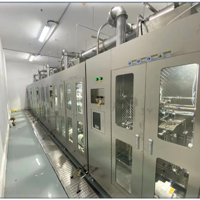
How Do You Calculate the Required Capacity of a Silane Abatement Scrubber?
Introduction
Silane (SiH₄) is a highly reactive, pyrophoric gas widely used in semiconductor manufacturing, photovoltaic production, thin-film deposition, and other advanced industrial processes. Although silane plays an important role in chemical vapor deposition (CVD) and related applications, it presents significant safety and environmental challenges. When released into air, silane can ignite spontaneously under suitable conditions, creating a risk of fire, equipment damage, and hazardous byproducts.
A silane abatement scrubber is designed to treat silane-containing exhaust before it is discharged into the facility’s exhaust system or atmosphere. Selecting the correct scrubber capacity is essential for achieving effective gas treatment, maintaining process stability, and meeting applicable safety and environmental requirements.
However, calculating the required capacity of a silane abatement scrubber is not simply a matter of matching the equipment to the exhaust pipe diameter. Engineers must consider the maximum silane flow rate, exhaust carrier-gas volume, silane concentration, operating pressure, process duty cycle, abatement efficiency, and potential peak-flow conditions.
This technical guide explains how to calculate the required capacity of a silane abatement scrubber, which engineering parameters must be collected, and how to select an appropriate system for semiconductor and industrial gas applications.
1. Understand the Meaning of Silane Abatement Scrubber Capacity
Before performing calculations, it is important to distinguish between several capacity parameters commonly used in silane abatement systems.
1.1 Gas Flow Capacity
Gas flow capacity refers to the volume of exhaust gas that the abatement system can process within a specified period. It is commonly expressed in standard liters per minute (SLPM), standard cubic meters per hour (Nm³/h or Sm³/h), or actual volumetric flow units.
This parameter includes the carrier gas and other exhaust constituents, not just silane.
For example, a process may use a relatively small quantity of silane diluted in nitrogen. Although the silane flow is low, the total exhaust flow can be significantly higher because of nitrogen dilution and additional process gases.
1.2 Silane Treatment Capacity
Silane treatment capacity describes the amount of silane the system can safely process and abate over time. Depending on the equipment and application, it may be expressed as a mass flow rate, such as grams per minute, or as a standard volumetric flow rate of pure silane.
A system rated for a particular total exhaust flow does not automatically have sufficient silane treatment capacity. Both parameters must be verified against the manufacturer’s design specifications.
1.3 Abatement Efficiency
Abatement efficiency represents the proportion of the target gas removed or converted by the treatment system.
It is calculated as:
Abatement efficiency (%) = [(Inlet concentration − Outlet concentration) / Inlet concentration] × 100%
For a silane abatement system, the required performance depends on the process application, applicable environmental regulations, facility safety requirements, and the technology used.
High removal efficiency alone does not demonstrate that a scrubber has adequate capacity. The equipment must also maintain the required performance at the maximum expected silane loading and exhaust flow.

2. Collect the Essential Design Parameters
Accurate sizing begins with reliable process data. Before selecting a silane abatement scrubber, engineers should collect the following information.
2.1 Maximum Silane Flow Rate
Determine the maximum silane delivery rate under normal operation, startup, shutdown, maintenance, and any other relevant operating conditions.
The flow rate may be obtained from the process recipe, mass flow controller (MFC) specifications, gas delivery system design, or equipment manufacturer’s documentation.
For preliminary calculations, distinguish between:
- Normal silane flow during steady-state processing.
- Maximum instantaneous flow permitted by the process equipment.
- The combined flow from multiple tools or process chambers.
- Potential abnormal releases that require separate safety analysis.
The maximum normal operating flow should be used for initial capacity calculations rather than the average flow alone.
2.2 Silane Concentration
Silane concentration is commonly expressed as a volume fraction or percentage of the total gas stream.
For example, a mixture containing 2% silane by volume contains approximately 0.02 units of silane volume per unit of total mixture volume, assuming the components are compared on the same temperature and pressure basis.
The concentration affects the chemical loading and may influence the applicable treatment technology, reaction characteristics, and safety requirements.
2.3 Total Exhaust Flow Rate
Determine the combined exhaust flow from silane, carrier gases, purge gases, and other compatible process exhaust streams.
The total flow rate is important because the abatement system must handle the actual gas volume entering its treatment section.
Do not assume that the silane flow rate represents the total exhaust flow rate.
2.4 Operating Pressure and Temperature
Record the pressure and temperature at the relevant measurement point. Flow values reported under standard conditions cannot be directly compared with actual volumetric flow measurements without conversion.
Engineers should also verify the reference conditions used by the supplier. The definitions of standard temperature and pressure may differ between specifications, so SLPM, Nm³/h, and Sm³/h should not be treated as interchangeable without checking their reference conditions.
2.5 Number of Connected Process Tools
For facilities with multiple semiconductor tools, calculate the expected combined exhaust demand and determine whether the tools operate simultaneously.
The total connected flow is not always equal to the maximum simultaneous flow. However, any reduction based on simultaneous operation must be supported by process scheduling data, interlocks, and the facility’s operating philosophy.
3. Calculate the Silane Volumetric Flow Rate
The first calculation is to establish the silane flow rate in a consistent set of units.
If the silane flow is already measured in SLPM, the standard volumetric flow rate can be used directly, provided the reference conditions are known.
To convert SLPM to standard cubic meters per hour:
Q (m³/h) = Q (SLPM) × 60 / 1,000
For example, a silane flow of 5 SLPM corresponds to:
Q = 5 × 60 / 1,000
Q = 0.30 standard m³/h
This value represents the standard volumetric flow of silane, not the total exhaust flow.
If the flow is expressed in mass units, such as grams per minute, the equivalent standard volumetric flow can be calculated using the molecular weight and the specified reference conditions.
The ideal-gas relationship is:
Q = ṁ × R × T / (P × M)
Where:
- Q = volumetric flow rate.
- ṁ = mass flow rate.
- R = universal gas constant.
- T = absolute reference temperature.
- P = absolute reference pressure.
- M = molecular weight of silane.
For silane, SiH₄, the molecular weight is approximately 32.12 g/mol.
The temperature and pressure used in this equation must correspond to the reference conditions for the desired standard volumetric flow. If actual volumetric flow is required, use the actual gas temperature and absolute pressure instead.
4. Calculate the Total Exhaust Gas Flow
After determining the silane flow, calculate the total exhaust flow entering the abatement system.
For a simplified gas mixture, the total standard volumetric flow is the sum of the individual component flows when all values use the same reference conditions:
Q_total = Q_silane + Q_carrier gas + Q_purge gas + Q_other gases
Consider the following illustrative example:
A process exhaust contains:
- Silane: 5 SLPM.
- Nitrogen carrier gas: 95 SLPM.
- Additional compatible exhaust gas: 100 SLPM.
The combined flow is:
Q_total = 5 + 95 + 100
Q_total = 200 SLPM
Converting this value:
Q_total = 200 × 60 / 1,000
Q_total = 12 standard m³/h
The abatement equipment must therefore be evaluated for a total exhaust flow of 12 standard m³/h, in addition to its ability to treat the incoming silane load.
This example is a flow-accounting exercise, not a recommended silane operating condition. The compatibility of every gas stream must be confirmed before combining exhaust sources.
5. Determine the Required Design Capacity
Once the maximum total exhaust flow has been established, engineers can determine the preliminary design flow capacity.
A common preliminary approach is to apply a documented engineering margin to the maximum expected operating flow:
Q_design = Q_max × (1 + S)
Where:
- Q_design = preliminary design flow capacity.
- Q_max = maximum expected normal operating exhaust flow.
- S = selected design margin expressed as a decimal.
Suppose the maximum expected exhaust flow is 200 SLPM and the engineering team selects a 20% margin for preliminary evaluation.
Q_design = 200 × 1.20
Q_design = 240 SLPM
In this example, 240 SLPM is the preliminary flow-sizing target.
The 20% margin is illustrative only. It is not a universal requirement or a substitute for the equipment manufacturer’s design criteria. The appropriate margin depends on measurement uncertainty, future process expansion, operating variability, and the selected abatement technology.
Engineers should avoid applying an arbitrary margin without checking whether the system can safely accommodate the resulting flow, pressure drop, heat load, and chemical loading.
6. Evaluate Silane Mass Loading and Chemical Treatment Requirements
Flow capacity is only one part of scrubber sizing. The system must also be designed for the chemical load associated with the incoming silane.
If the silane flow is known in standard volumetric units, its molar flow can be estimated using the ideal-gas equation:
ṅ = P × Q / (R × T)
Where ṅ is the molar flow rate and Q is the standard volumetric flow expressed in compatible units.
The corresponding silane mass flow is:
ṁ = ṅ × M
Where M is the molecular weight of silane.
For example, a silane stream of 5 SLPM corresponds to approximately 0.20 mol/min at reference conditions near 0°C and 1 atmosphere. Multiplying by the molecular weight of 32.12 g/mol gives a silane mass flow of approximately 6.4 g/min.
The precise result depends on the reference temperature and pressure.
This mass-flow calculation helps engineers quantify the incoming chemical load. However, it does not independently establish the capacity of a particular abatement technology.
Silane abatement may involve oxidation, combustion, thermal treatment, or other engineered processes. Depending on the technology, important design considerations include reaction heat, oxygen availability, dilution requirements, reaction products, dust formation, and downstream treatment needs.
Because silane is pyrophoric, the system must be designed by qualified specialists. Operators should not attempt to establish a safe treatment configuration by simply increasing oxygen or changing gas mixtures based on a calculation.
7. Account for Multiple Tools and Simultaneous Operation
Semiconductor facilities may connect several process tools to a shared abatement system. In this situation, sizing must consider the maximum credible combined demand.
For example, if four process tools each have a maximum exhaust flow of 200 SLPM, the total connected flow is:
Q_connected = 4 × 200
Q_connected = 800 SLPM
If all four tools can operate simultaneously, the preliminary system flow requirement must account for that combined load, together with any additional margin justified by the design basis.
If the facility uses a validated control system to prevent certain tools from operating simultaneously, the design team may be able to use a lower maximum simultaneous flow. Such an approach requires documented operating constraints and an appropriate failure analysis.
The assessment should also consider startup and shutdown sequences, purge cycles, recipe changes, maintenance procedures, and other operating conditions that may create temporary flow peaks.
A system sized only for typical steady-state operation may be inadequate when several tools purge or transition between process steps at the same time.
8. Verify Abatement Efficiency and Outlet Requirements
The selected scrubber must achieve the required silane destruction or removal performance at the design operating conditions.
The required efficiency should be established from applicable environmental permits, facility engineering standards, process requirements, and the manufacturer’s validated performance data.
For example, if an inlet stream contains 1,000 ppm of a target species and the system achieves 99% removal, the theoretical outlet concentration is:
C_out = 1,000 × (1 − 0.99)
C_out = 10 ppm
This calculation illustrates the relationship between inlet concentration and removal efficiency. It does not establish that a particular silane abatement system can achieve this performance.
For reactive gases, engineers must also evaluate the reliability of the treatment process, the possibility of bypass or breakthrough, and the behavior of reaction products.
Performance verification should use an appropriate measurement method and a defined test protocol. Inlet and outlet measurements must be comparable, and the testing approach must account for the characteristics of the gas stream.
9. Consider Pressure Drop, Utilities, and Maintenance Requirements
A correctly sized abatement system must satisfy more than the nominal gas-flow requirement.
Pressure Drop
The scrubber, connecting pipework, valves, filters, and downstream exhaust equipment contribute to pressure drop. Excessive resistance can affect the process tool’s exhaust performance and create operational problems.
The supplier should provide pressure-drop data at the required flow and operating conditions.
Utility Requirements
Depending on the technology, the system may require electrical power, cooling water, compressed air, fuel, or other utilities. Confirm that the available utilities can support maximum operating demand and any startup requirements.
Byproduct Management
Silane treatment can produce reaction products that require downstream handling. Depending on the treatment method and process conditions, these may include silica-based particulate matter and other combustion or reaction products.
The abatement system should include appropriate measures for particulate management, exhaust compatibility, and maintenance access as required by the design.
Maintenance and Availability
Review the manufacturer’s recommended service intervals, consumable replacement schedule, expected maintenance downtime, and availability of spare parts.
For semiconductor production, system availability can be as important as nominal treatment capacity. A system that frequently requires cleaning or maintenance may not meet the facility’s operational needs even if its rated flow appears sufficient.
10. Common Mistakes in Silane Scrubber Sizing
Several mistakes can result in undersized or unsuitable abatement equipment.
Using silane flow as the total exhaust flow: The carrier gas and other compatible exhaust streams must also be included.
Using average flow instead of maximum operating flow: Peak demand and process transitions may determine the actual capacity requirement.
Ignoring reference conditions: Standard and actual volumetric flows differ with temperature and pressure.
Selecting equipment solely by SLPM rating: Chemical loading, treatment efficiency, pressure drop, and utility requirements must also be checked.
Applying an arbitrary safety margin: A margin should be justified by documented engineering assumptions and verified against the selected equipment’s operating limits.
Ignoring byproducts and maintenance: Reaction products, particulate loading, and maintenance requirements can affect the suitability of the system.
Combining incompatible exhaust streams: Gas compatibility must be assessed before designing a shared abatement system.

Conclusion
Calculating the required capacity of a silane abatement scrubber requires a systematic evaluation of total exhaust flow, maximum silane loading, gas concentration, operating conditions, treatment efficiency, and the number of connected process tools.
The basic sizing process begins by establishing the maximum expected silane flow and converting all gas flows to consistent reference conditions. Engineers then calculate the total exhaust demand, select a justified preliminary design margin, determine the silane mass loading, and verify that the proposed equipment can meet the required treatment performance.
However, flow calculations alone cannot establish that a silane abatement system is safe or suitable. Because silane is highly reactive and pyrophoric, final equipment selection must be supported by a qualified engineering assessment, manufacturer performance data, process hazard analysis, and applicable facility and regulatory requirements.
For semiconductor manufacturers, photovoltaic production facilities, and specialty-gas users, a properly sized silane abatement scrubber helps support safe exhaust treatment, stable process operation, and reliable long-term performance. Working with an experienced abatement system manufacturer is essential to ensure that the selected equipment matches both the chemical characteristics of the exhaust and the actual operating requirements of the facility.
For more about how do you calculate the required capacity of a silane abatement scrubber, you can pay a visit to Jewellok at https://www.jewellok.com/ for more info.
-
764L Stainless Steel Union Tee High Purity Fitting Union Tee Reducing Tubing Connection
-
Ultra High Purity Stainless Steel Compressed Gas Changeover Manifold Panel System For Integrated Gas Supply System
-
UHP Metal Gasket Face Seal Fittings Vacuum Coupling Metal Face Seal Join Long Gland And Short Gland
-
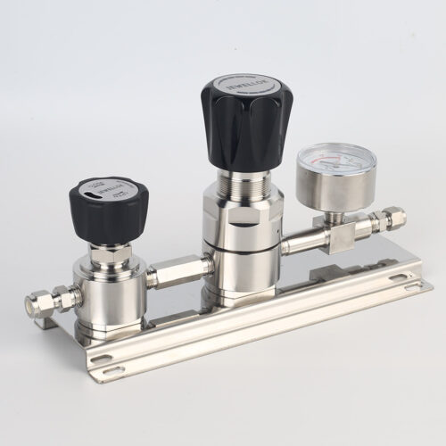
High Purity High Flow Pressure Control Regulators & Valves Gas Stick Assemblies JSR-2TG Series
-
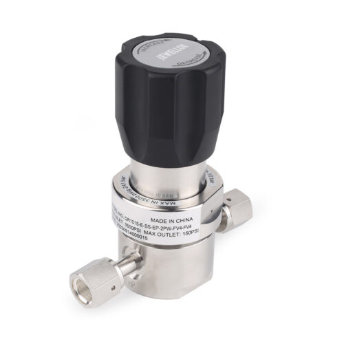
316L Vim Var Stainless Steel Ultra High Purity Gas Pressure Reducing Valve For Corrosive Specialty Gas Distribution
-
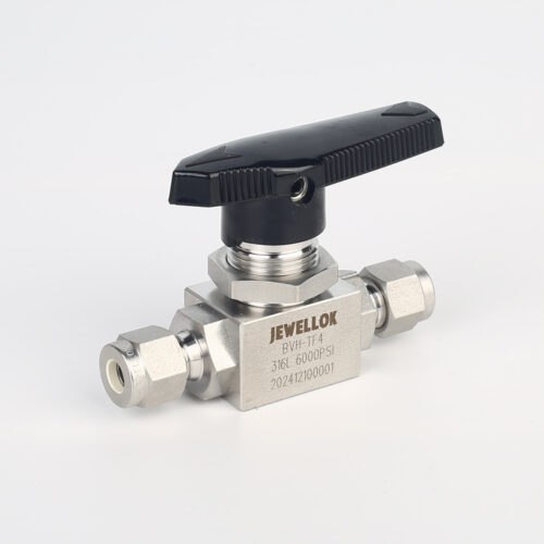
High Purity High Pressure 316 Stainless Steel Ball Valves JBV1 Series From High Pressure Ball Valve Manufacturer And Supplier In China
-
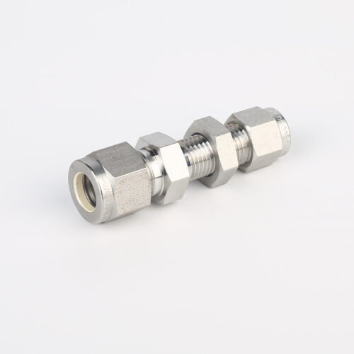
775L Bulkhead Reducing Union | Stainless Steel High Purity Double Ferrule Bulkhead Reducing Unions
-
JR1000 Series UHP Ultra High Purity Single Stage Pressure Reducing Regulator And Low To Intermediate Flow