
Valves Manufacturer Tel: +86 13380377051
How to Design a Laboratory Gas Distribution System for Safe Gas Delivery
Introduction and Design Scope
A laboratory gas distribution system carries gases from their source—cylinders, cryogenic dewars, or bulk tanks—through regulators, manifolds, and piping to the points of use. Done well, the design delivers the right gas at the right purity, pressure, and flow while containing the hazards of pressurized, flammable, toxic, corrosive, and asphyxiant gases; done poorly, it becomes one of the most dangerous utilities in a building. Safe gas delivery is not achieved by a single device but by a sequence of engineering decisions: a gas audit, code analysis, source location, material selection, pressure control, engineered safeguards, and formal commissioning. This article walks through that sequence.
Audit Gases, Hazards, and Demand
The first step in designing any gas installation, new or retrofit, is an audit of the gases required at each location: what each instrument needs, its purity grade, required delivery pressure, and peak flow demand. This audit drives everything downstream—pipe sizing, storage arrangements, and supply mode.
Classify each gas by hazard. Codes such as NFPA 55 distinguish inert, flammable, oxidizing, corrosive, toxic, pyrophoric, and unstable-reactive gases, and many gases carry overlapping hazards: chlorine is simultaneously an oxidizer, a corrosive, and a toxin; silane is pyrophoric and flammable. Even inert gases are not “safe”: nitrogen, argon, and helium are simple asphyxiants, and OSHA defines an oxygen-deficient atmosphere as one below 19.5% oxygen by volume.
For sizing, base the design on documented simultaneous demand at all use points, plus an expansion allowance the owner can justify for future growth, and calculate pressure losses through every component so that the minimum pressure required at each instrument is available at peak flow, not just at the source.
Codes and Source Location
Design begins with identifying the locally adopted requirements and applicable editions together with the owner and the authority having jurisdiction (AHJ)—codes are legally binding only where adopted. In the United States, the framework most commonly applied includes NFPA 55 (Compressed Gases and Cryogenic Fluids Code), NFPA 45 (Fire Protection for Laboratories Using Chemicals), CGA P-1 (Safe Handling of Compressed Gases in Containers), and OSHA 29 CFR 1910.101. NFPA 55 provides fundamental safeguards for the installation, storage, use, and handling of compressed gases and sets maximum allowable quantities (MAQ) per control area, above which an emergency plan is required; NFPA 45 limits gas quantities in laboratory units by reference to NFPA 55 and requires that cylinders not needed for current work be stored outside the laboratory. Permitted quantities depend on the adopted edition, occupancy classification, control-area design, and protection arrangements, so they must be established project-specifically with the AHJ.
The practical design consequence: keep cylinders out of the laboratory wherever possible. Store them in a dedicated, secure, ventilated location, keep incompatible gases separated, and keep full cylinders segregated from empty ones.
For continuous supply, connect cylinders in banks through a switchover manifold so that one bank can be vented, replenished, and purged while a second bank continues to supply the system; semi-automatic switchover systems switch from a primary cylinder or bank to a reserve without interrupting the gas supply. Design the manifold to prevent unintended crossflow between cylinders, using service-appropriate isolation and backflow controls, and never connect incompatible gases to a common manifold.
Select Materials, Joints, and Cleanliness
Material selection starts with gas compatibility for the specific service—alloy, seals, concentration, moisture, temperature, and pressure—then considers purity requirements and life-cycle cost. As an example, one national laboratory standard specifies Type K copper tubing with silver-brazed joints, or ASTM A269 stainless steel with automatically orbital-welded joints, as the preferred piping materials cleaned for hydrogen and methane systems. Stainless steel is not universally suitable for corrosive gases—particularly in wet chlorine service—so compatibility must be verified gas by gas. Regulator wetted parts follow the same logic: application, gas service, and required delivery pressure all influence regulator selection. Metal diaphragms can reduce outgassing and permeation relative to elastomers, and low-cost materials can fail to maintain the moisture purity of the gas in the cylinder.
Cleanliness is a design requirement, not an afterthought. Specify oxygen-compatible components with documented oxygen-service cleanliness using the applicable approved standard, such as CGA G-4.1, and protect cleaned surfaces against recontamination: components should arrive cleaned, capped, and certified, and remain sealed until installation.
Stage the Pressure
Cylinders store gas at high pressure—commonly 2,000–3,000 psig—while instruments typically need far less. Select the pressure-reduction stages according to source pressure, required delivery pressure, flow demand, and regulator performance: a source or manifold regulator drops cylinder pressure to an intermediate distribution pressure, and point-of-use line regulation is added where the application needs it. A regulator is a pressure-control device, not a flow-control device.
Two-stage regulation is chosen where stable delivery matters: a single-stage regulator exhibits a “decaying inlet” characteristic—outlet pressure rises as cylinder pressure falls—whereas a two-stage regulator compensates for the changing cylinder pressure and reduces delivery-pressure sensitivity, which is why it is recommended for analytical instruments such as gas chromatographs. But staging alone is not a safety control. Regulators can fail or creep, so specify independent downstream overpressure protection, selected and sized for the actual system by a qualified pressure-system designer; a relief valve installed downstream of the regulator is one documented protection against creep.
Engineer the Safeguards
Safeguards layer on top of containment. Where codes require hazardous gases to be isolated in gas cabinets, typical requirements include not less than 12-gauge steel construction, self-closing access doors, ventilation with defined face velocity at access openings, internal sprinkler protection, and a cylinder-count limit per cabinet. Enclosure, ventilation, fire protection, detection, and automatic-shutdown requirements are determined from the gas hazards, quantities, occupancy, and adopted codes. Institutional guidance illustrates the layered approach: highly toxic and pyrophoric gases are stored in sprinklered gas cabinets with controllers that shut off gas on detection, excess-flow control, exhaust monitoring with interlock shutdown on exhaust loss, and manual emergency shutoff at the cabinet.
Detection is engineered, not sprinkled in. Place sensors based on gas density and likely release points—lighter-than-air gases such as hydrogen accumulate high, heavier-than-air gases pool low—while also considering airflow patterns, release temperature, occupied zones, and manufacturer guidance. Detection systems should be tied to automatic controls that shut off the gas supply in the event of a leak, with alarms set before dangerous concentrations are reached. Oxygen monitoring follows an assessment of credible deficiency and enrichment scenarios where asphyxiant gases or cryogenic liquids are stored or dispensed; deficiency alarms are referenced to the 19.5% OSHA threshold, and enrichment is monitored separately where it is credible.
Emergency isolation completes the safety layer. Manual and automatically actuated emergency shutoff valves should be installed with ready access at the point of use and at the gas source, clearly labeled. Know each device’s limits: an excess-flow valve halts flow only when its specified trip conditions are reached, so it will not detect every leak; a flashback arrestor addresses flame propagation and is not the same function as a reverse-flow check valve. For corrosive and toxic gases, add purge capability with a compatible purge gas and protection against backflow into the purge supply. Regulators in corrosive service should be purged with an inert gas such as nitrogen during shutdowns, and the purge method and sequence should be validated for the service—dilution purging, alternately pressurizing and venting the regulator and lines through a safety vent, is one documented approach for removing residual gas and ambient moisture before cylinder changeout. Purge and relief discharges must be vented or treated to a safe location, never into an occupied space.
Commission Formally
Commissioning must be measurable and documented. First, establish the piping code of record during design according to its actual scope, the gas service, design conditions, and jurisdictional requirements—a laboratory location alone does not establish whether ASME B31.3, ASME B31.9, or another code governs.
Mechanical-integrity pressure testing verifies the piping against its design pressure. Perform it under an approved procedure that specifies the governing code’s test pressure, a compatible medium such as dry, oil-free nitrogen, duration, and acceptance criteria. Because pneumatic testing stores significant energy, exclude components not rated for the test pressure and never adjust a pressurized joint.
Service leak-tightness testing is a separate exercise: industry guidance is to leak-test at or below the system’s maximum allowable working pressure with a suitable medium, beginning with a preliminary low-pressure check to locate major leaks before full pressurization . The acceptance program should also verify cleanliness and point-of-use purity where specified, confirm the identity of each outlet and check for cross-connections, and demonstrate pressure and flow performance at each use point. Finally, test the safety controls end to end: gas detection, alarms, ventilation interlocks, and automatic and manual emergency shutoff. Handover should include as-built drawings, material certificates, test records, labeling, and maintenance instructions.
Maintain and Improve
A gas system is never “finished.” Include regulators, relief devices, and flexible connectors in a maintenance program based on their manufacturers’ instructions, and maintain other gas detectors the same way. Calibrate and function-test oxygen monitors according to applicable requirements and the approved monitoring program. Cylinders must remain secured, with protective caps fitted where provided when disconnected and stored, segregated by hazard class, and returned promptly when empty.
Designing for safe gas delivery means respecting the full hazard: stored energy in pressure, fire potential in flammables and oxidizers, invisibility of asphyxiants, and the slow chemical attack of corrosives. The system that accounts for all of them will deliver gas safely and reliably for the life of the laboratory.
For more about how to design a laboratory gas distribution system for safe gas delivery, you can pay a visit to Jewellok at https://www.jewellok.com/ for more info.
-
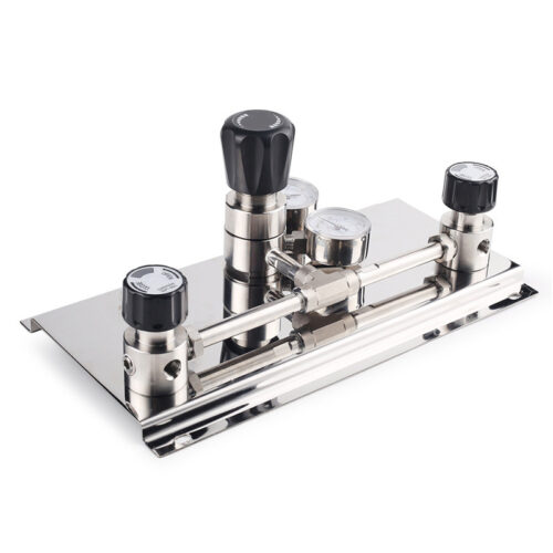
High Purity Semi-Auto Stainless Steel Changeover Manifold System, Nitrogen High Pressure Control Panel With Semiconductor Valve Manifold Box Diaphragm Valves
-
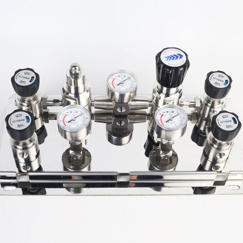
Semi Automatic Gas Changeover Manifold System Manual Changeover Manifold Panel Single Stage Automatic Switchover Board
-
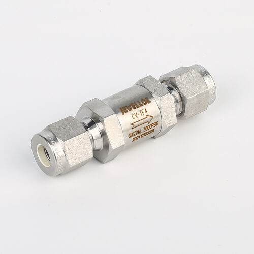
High Pressure High-Purity Welded Check Valves And Low Cracking Pressure Check Valve JCV1 Series
-
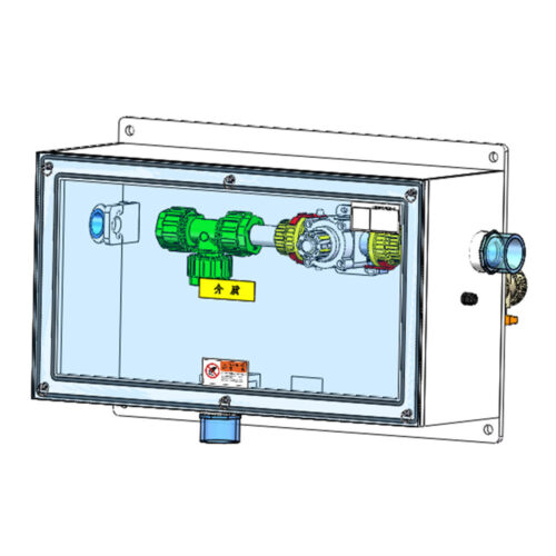
FT-BOX JW-FTB-C Valve Manifold Panels And Boxes With High Purity Configurable Systems
-
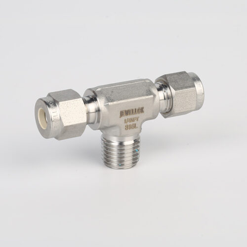
772L Male Branch Tee | Stainless Steel High-Purity Tube Fitting Male Branch Tee
-
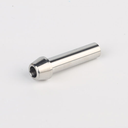
767LP Port Connector Ultra High Purity VCJ Metal Gasket Face Seal Tube Fittings
-
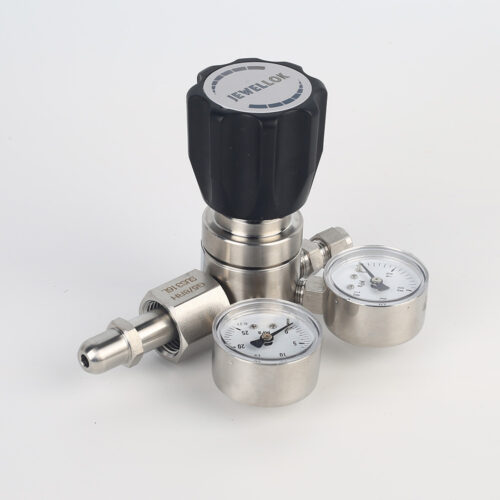
High Purity High Pressure Specialty Gas Pressure Regulators Specialty Gases Pipeline Engineering Equipments Manufacturer And Supplier
-
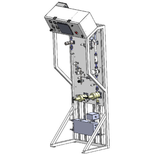
Semiconductor High Purity High Pressure Specialty Gas Bottle Gas Cylinder Storage Cabinet And Gas Pressure Regulating Cabinet